NEW: Learning electronics? Ask your questions on the new Electronics Questions & Answers site hosted by CircuitLab.
Basic Electronics » Geiger Counter Schematic Help
|
March 18, 2011 by Steven 
|
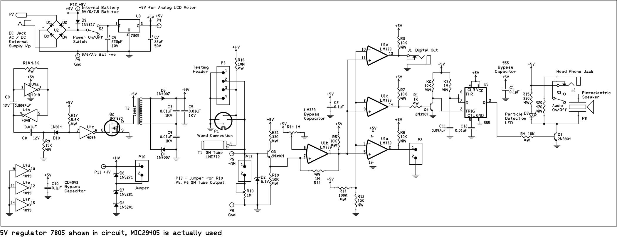
With the recent events at the Fukushima Dai-ichi nuclear power plant, I thought it would be pretty cool to build a Geiger Counter and hook it up to my NerdKit for interfacing with my computer. I've found this article which explains the building process pretty well, and also includes a schematic:
Unfortunately, the section that describes the circuit really doesn't explain how the circuit works. This may be a huge request, but could somebody do a writeup on this circuit that explains what each component does to get the end result? I've been looking over the circuit but my inexperience with such schematics isn't helping at all. |
|---|---|
|
March 18, 2011 by 6ofhalfdozen |
Steven, I am not an electrical guru, but from what i can read most of the schematic makes sense, althought the power part is really messy. I have broken out a few of the sections below with what I believe they do. Any of the pros around here should feel free to jump in and point out where i am going wrong. hopefully it helps, but if you want more detail I will try. --Upper Left Corner : Diode Bridge "D10" - I believe this is a break out for a 110VAC to 25VDC wall wort, dunno why they did it, but its there. --Lower Left Corner : "D9", a 9v battery, some caps and a 7805 - This looks like a way to convert the 25VDC to 5VDC with decent current capacity and have a battery backup. The 7805 portion is very similar to how it is used on the NK. I think the Vcc leaving this section is being used to feed the "Vcc" sections elsewhere in the diagram, but I migh be wrong. -- Left Central: U1a-d, "D1", caps, resistors,Q1, T1 left side - This is a square wave pulse generator to feed the transformer T1. I have seen other diagrams where a hex inverter IC (U1 pins a-d) is used with an ResistorCapacitor setup to create a square wave output train. (think of this section as heavy duty 555, that doesn't use a 555 per say) -- Right Upper Central: T1 right side,D2-6, caps - This section on the right side of T1, is the high power DC generation section. The transformer steps the squarewave DC up to a higher voltage ugly square wave and then the diodes and caps clean it up to a semi-steady DC. The Zeners, D4-6, effectively "regulate" the voltage to the GM tube at ~500Vdc. R4 is of course to keep the current down and prevent arcing inside the GM tube. --MidFarRight: Q2, U1e, caps, resists - The GM tube outputs a very fast (nano-microsec) but very small pulse. the transistor and inverter with the help of the capacitor and resistor, shape the pulses to +5/0V in the proper orientation for U2 and keep the high voltage from getting to the U2. The transistor acts like an crude amplifier in this portion, making the tiny blips out of the GM tube closer to logic transistions. --Lower Right Central: U2, caps, resistors, speaker, LED, headphone jack - U2 is a 555 being used as a pulse stretcher to take the ysec pulses from the previous section and convert them into a pulse that is visible when flashed on an LED or Audible when put on the speaker. This is a very typical use for 555's and most datasheets have a diagram of them being used like this. I am going to assume the LED, speaker, and headphone jack are pretty self-explanitory. |
|
March 18, 2011 by mongo 
|
6, You got a good picture for not being a "Guru" Geiger counters use the pulse of conductivity in the tube from radioactive particles that cause a little ionization in the tube. These pulses are very very short, so there needs to be a little conditioning to make them human friendly. That is indeed a voltage multiplier in the upper right section and regulated to 475V from what I pick up in the data sheets. The 10M resistor is to limit the current but not for arc suppression. It's more to protect the input to the 3904 and inverter. Otherwise, the voltage spike could zap them. The 4049 is a CMOS chip and they are really sensitive to things like over-voltage conditions. The inverters that have the resistors and capacitors attached are an oscillator. They in turn feed the next two in parallel to drive a little more current to the FET, which then drives the transformer for the high voltage generator. |
Please log in to post a reply.
|
Did you know that electric fields behave differently in different materials? Learn more...
|


Copyright © 2013 by NerdKits, L.L.C.