March 03, 2011
by Ace

|
I want to build the LED heart with some modifications. Looking at heart_back.jpg from the project page, I see some additional parts on the board but I can't seem to find out what they are.
-
There is a resistor going from "a-11" on the breadboard (pin 1 of MCU) to hot on the side rail. Is this 100k?
-
There is a capacitor which looks to be going from MCU pin 7 to pin 8 (can't quite tell the exact location from the picture) What value is this, and where does it go exactly?
-
There is a gray & black capacitor at the bottom near the voltage regulator. What value is this and where is it connected?
-
On the right side of the board there is a square blue part near the voltage regulator. What is it and where is it connected?
-
There are two yellow wires which I'm confused about. The first goes from i-2 to i-6 on the right side of the breadboard near the top, the second is just below that and looks like it goes from f-9 to i-9. I can't see how these connect to anything else. Are these wires necessary?
Thank you. |
March 03, 2011
by 6ofhalfdozen
|
Hello Ace!
the NK guys are the final answer on this one, but here is what I can see/tell.
- I see brown black yellow gold, so yes, as far as I can tell it is 100kOhm.
- i actually think the red thing is a piece of electrical tape covering an overstripped wire. it doesn't look like any cap i have seen.
- I can't make out the markings, but I am assuming this is the power filter cap. i would believe it spans from 5Vout on the regulator to ground on the regulator.
- I am fairly certain it is a variable resistor/potentiometer, I have several identical looking ones who are 0-100Kohm. I can't trace all the wires, but I am thinking it is the brightness control for the either the LCD or the LEDs on the outer ring of the heart.
- I think those two wires were spares not used on this project build, as you mention they don't connect to anything.
hope that helps a little |
March 03, 2011
by Rick_S

|
The parts you are seeing on the board are mostly parts from an earlier version of the Nerdkit most of which don't "HAVE" to be installed in the current NK setup. I'll describe them to you though.
- The resistor you see going from pin1 to the 5V rail is what is commonly called a pullup resistor. The value isn't super critical. I commonly use a 10K resistor. The current NK setup just uses a jumper wire (or 0K resistor).
- The red thing is in fact a capacitor. You have one supplied with your kit as well, it is just not red. Most likely, the one you got is a yellowish color and would have 104 printed on it. (.1uf) This is commonly called a bypass capacitor as it is used to filter or bypass any ripples in the DC to ground. Thus providing cleaner power. This is part of your standard NK board setup.
- That would be a filter capacitor for the input power to the regulator. It would commonly be used if you use an alternate power source such as a wall power adapter. Batteries have clean power and would not require one. My guess is that they had used external power to operate this circuit at some time so they had the capacitor there to keep the power clean. Again, size isn't too critical, I have used anywhere from 10uf to 100uf. However, depending on your power source more or less may be needed. That capacitor would connect between your input power and ground.
- In the earlier NK setup, the LCD had it's contrast line (Pin3 of your LCD) connected to a variable resistor to adjust. In the current setup, they provide a fixed resistor for the LCD contrast. I'm not sure if they include those anymore, but if you build your kit per the guide, you don't need it.
- The two wires I believe were just there to act as some sort of retainer to hold the longer wires in place. They serve no purpose to the circuit.
Rick |
March 05, 2011
by hevans
(NerdKits Staff)

|
Hi Ace,
The explanations you received above were in fact spot on. Great questions, and thanks Rick and 6ofhalfdozen, for jumping in.
Humberto |
March 05, 2011
by Ace
|
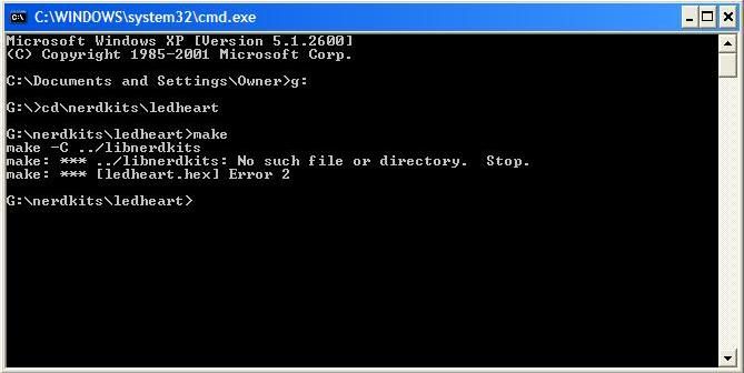
Thank you all for your help. I'm having problems uploading the source code for this project. I copied the makefile from the initialload folder and changed all occurances of "initialload" in that makefile to "ledheart" with programmer's notepad. When I type "make" I get:
make -C ../libnerdkits
make: *** ../libnerdkits: No such file or directory.  Stop.
make: *** [ledheart.hex] Error 2
The only files in my ledheart folder are the c file and the makefile. I'm sure it's something easy that I'm just overlooking. Thank you. |
March 05, 2011
by Ralphxyz

|
We'd need a screen shot of your command line but I believe you are not in the initialload folder.
If you were on Windows you should have something like C:NerdkitsCodeInitialload you would do a cd NerdkitsCodeInitialload
and have a "C:Initialload" prompt where you would type "make" (no quotes of course).
If you still have problems give us a screenshot (alt/print screen in windows).
Ralph |
March 05, 2011
by Ace
|
Here's a screen shot:
|
March 05, 2011
by Rick_S
|
The makefiles supplied with the nerdkits code expect a certain folder structure. If you were to move your ledheart folder into the code folder you downloaded, then your error will most likely go away. make is looking for the folder ../libnerdkits to compile the lcd.c , uart.c , and delay.c files. Since you are running make withing a folder that isn't within the code folder, it isn't finding the files needed to compile.
Your folder structure would be something like this:
code
   |
   |+
     libnerdkits
   |
   |+
     ledheart
Rick |
March 05, 2011
by Rick_S
|
Of course there would be other folders within the code folder as well... |
March 05, 2011
by Ace
|
Thank you Rick, that got it working |
March 05, 2011
by Ace
|
Could you add a potentiometer somewhere in the circuit to vary the speed of the lights? That could get interesting. |
March 05, 2011
by hevans
(NerdKits Staff)
|
Hi Ace,
You most definitely could do something like that. Modifying the code might be a bit tricky, but I'm sure with a little of time and poking around you could make that happen.
Humberto |
March 06, 2011
by Ace
|
In the mean time I'm trying to modify the code so that the LEDs are turned off when they are not brightening or dimming. Right now they are always on, but some are dimmer than others, which I think is how the original code is supposed to work. The only thing I've managed to do is turn off either the row or column completely, which is not what I want. So how can I do this? I've tried numerous things to no avail. |
March 07, 2011
by hevans
(NerdKits Staff)
|
Hi Ace,
I very much recommend you take the time and work through this solution yourself. Admittedly, where the minimum cutoff actually happens isn't very clear in the code, but if you try to follow how the duty cycle gets incremented slowly, reaches a max, and then goes all the way down to its lowest value I think you will be able to find the part of the code you are looking for. If you have questions about a specific part of the code, or would like a little more direction I would be glad to help.
Humberto |
March 08, 2011
by Ace
|
Hi Humberto
I'd like a little more direction please. Thank you. |
March 10, 2011
by hevans
(NerdKits Staff)
|
Hi Ace,
Follow the path of the code. See if you can explain to me where in the main loop the actual brightness of each LED is getting set. I think that will lead you to the solution.
Humberto |
March 15, 2011
by Ace
|
Humberto,
I have figured it out. It was in the //random twinkling effect section of the code.
I want to add more lights, so I chose PB0, PD6 and PD7; and I want to add a potentiometer to PC0 to change the speed of the lights. I started with adding lights but they aren't working. Here's what I changed (the first line is line 100 in the original code):
inline void ledarray_all_off() {
// turn off all row drivers
DDRC &= ~(1<<PC5);
PORTC &= ~(1<<PC5);

// turn off all column drivers
DDRC &= ~( (1<<PC1) | (1<<PC2) | (1<<PC3) | (1<<PC4) | (1<<PD6) | (1<<PD7) );
PORTC &= ~( (1<<PC1) | (1<<PC2) | (1<<PC3) | (1<<PC4) | (1<<PD6)| (1<<PD7) );
DDRB &= ~( (1<<PB0) | (1<<PB1) | (1<<PB2) | (1<<PB3) | (1<<PB4) | (1<<PB5) );
PORTB &= ~( (1<<PB0) | (1<<PB1) | (1<<PB2) | (1<<PB3) | (1<<PB4) |(1<<PB5) );
}
I also changed this (starts with line 155 of the original code):
void ledarray_init() {
incrementor = 0;

// Timer0 CK/8 (7000Hz)
TCCR0B = (1<<CS01) | (0<<CS00);
TIMSK0 = (1<<TOIE0);

// outputs (set row drivers high for off)
DDRC &= ~( (1<<PC1) | (1<<PC2) | (1<<PC3) | (1<<PC4) | (1<<PC5) | (1<<PD6) | (1<<PD7) );
DDRB &= ~( (1<<PB0)|(1<<PB1)|(1<<PB2)|(1<<PB3)|(1<<PB4)|(1<<PB5) );
}
I did manage to shut off the lights at PC0, which will be where I put in the pot. But right now I'd like to get the lights working at the new ports. Thank you. |
March 17, 2011
by Ace
|
I altered the code some more, but now I'm getting errors trying to load it:
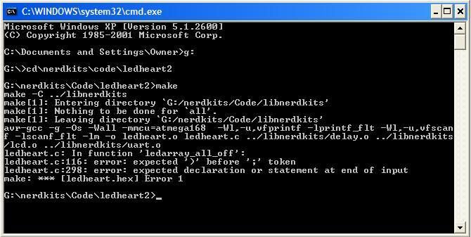
Here's the full code I modified. I don't need the lcd screen, so I removed all code referring to it (at least I think I removed it all). Again, I want to add lights to PB0, PD6, and PD7, and want to add a potentiometer to vary the speed of the lights at PC0.
// ledheart.c
// for NerdKits with ATmega168
// hevans@nerdkits.com
// modified from ledarray.c

#define F_CPU 14745600

#include <stdio.h>
#include <stdlib.h>

#include <avr/io.h>
#include <avr/interrupt.h>
#include <avr/pgmspace.h>
#include <inttypes.h>

#include "../libnerdkits/delay.h"
#include "../libnerdkits/uart.h"

// PIN DEFINITIONS:
//
// PC0 potentiometer to adjust speed
// PC5 ROW DRIVER
// PB0-PB5, PC1-PC4, PD6-PD7 : Column drivers 0 - 10
// We will use one row, and 10 column drivers. Switching the
// direction of every other LED, this allows us to drive 20 LEDs
#define ROWS 1
#define COLS 24

volatile uint8_t la_row;
volatile uint8_t duty[COLS]; //keeps the duty cycle of every LED: 0 - never on, 64 - all on
volatile uint8_t incrementor;

void adc_init(){
  PORTC |= (1<<PC0);
 // pot to change speed of lights
 ADMUX = 0;
 ADCSRA = (1<<ADEN) | (1<<ADPS2) | (1<<ADPS1) | (1<<ADPS0);
 ADCSRA |= (1<<ADSC);
 }

//duty 0 - 64
void set_duty(uint8_t j, uint8_t the_duty) {
  if(j < COLS){
    duty[j] = (the_duty >  64) ? 64 : the_duty;
  }
}

//set all the LEDs to full duty
void full_duty(){
  uint8_t j;
  for(j=0;j<COLS;j++){
    duty[j] = 64;
  }
}

//retrieve duty
inline uint8_t duty_get(uint8_t j) {
  if(j < COLS) {
    return duty[j];
  } else {
    return 0;
  }
}

//shortcut to set duty full on or full off
inline void ledarray_set(uint8_t j, uint8_t onoff) {
  if(j < COLS) {
    if(onoff) {
      duty[j] = 64;
    } else {
      duty[j] = 0;
    }
  }
}

inline void ledarray_set_columndriver(uint8_t j, uint8_t onoff, uint8_t sense) {
  // cols 0-5: PB0-5
  // cols 6-11: PC1-4, PD6-7
  if(j < 5) {
    if(onoff) {
      PORTB |= (1 << (PB1 + j));
    } else {
      PORTB &= ~(1<< (PB1 + j));
    }
    if(sense == onoff) {
      DDRB |= (1 << (PB1 + j));
    } else {
      DDRB &= ~(1 << (PB1 + j));
      PORTB &= ~(1 << (PB1 + j));
    }
  } else {
    if(onoff) {
      PORTC |= (1 << (PC1 + (j-5)));
    } else {
      PORTC &= ~(1<< (PC1 + (j-5)));
    }
    if(sense == onoff) {
      DDRC |= (1 << (PC1 + (j-5)));
    } else {
      DDRC &= ~(1 << (PC1 + (j-5)));
      PORTC &= ~(1 << (PC1 + (j-5)));
    }
  }
}

inline void ledarray_all_off() {
  // turn off all row drivers
  DDRC &= ~(1<<PC5);
  PORTC &= ~(1<<PC5);

  // turn off all column drivers
  DDRC &= ~( (1<<PC1) | (1<<PC2) | (1<<PC3) | (1<<PC4) );
  PORTC &= ~( (1<<PC1) | (1<<PC2) | (1<<PC3) | (1<<PC4) );
  DDRB &= ~( (1<<PB0) | (1<<PB1) | (1<<PB2) | (1<<PB3) | (1<<PB4) | (1<<PB5) );
  PORTB &= ~( (1<<PB0) | (1<<PB1) | (1<<PB2) | (1<<PB3) | (1<<PB4) | (1<<PB5) );
  DDRD &= ~( (1<<PD6) | (1<<PD7);
  PORTD &= ~( (1<<PD6) | (1<<PD7);
}

SIGNAL(SIG_OVERFLOW0) {

  //keep a counter to provide duty cycle
  incrementor++;
  if(incrementor == 64)
    incrementor = 0;

  // turn off old row driver
  ledarray_all_off();

  // increment row number
  if(++la_row == 2*ROWS)
    la_row = 0;

  // set column drivers appropriately
  uint8_t j;
  if(la_row%2 == 0) {
    // even la_row number: fill even columns
    for(j=0; j<COLS/2; j++) {
      //check duty for each LED, do not turn on if duty is less than incrementor
      if(duty[2*j] > incrementor)
        ledarray_set_columndriver(j, 1, 1);
      else
        ledarray_set_columndriver(j, 0, 1);
    }
    // activate row driver SINK
    PORTC &= ~(1 << (PC5));
    DDRC |= (1 << (PC5));
  } else {
    // odd la_row number: fill odd columns
    for(j=0; j<COLS/2; j++) {
      //check duty for each LED, do not turn on if duty is less than incrementor
      if(duty[2*j + 1] > incrementor)
        ledarray_set_columndriver(j, 0, 0);
      else
        ledarray_set_columndriver(j, 1, 0);
    }
    // activate row driver SOURCE
    PORTC |= (1 << (PC5));
    DDRC |= (1 << (PC5));
  }
}

void ledarray_init() {
  incrementor = 0;

  // Timer0 CK/8 (7000Hz)
  TCCR0B = (1<<CS01) | (0<<CS00);
  TIMSK0 = (1<<TOIE0);

  // outputs (set row drivers high for off)
  DDRC &= ~( (1<<PC1) | (1<<PC2) | (1<<PC3) | (1<<PC4) | (1<<PC5) );
  DDRB &= ~( (1<<PB0) | (1<<PB1) | (1<<PB2) | (1<<PB3) | (1<<PB4) | (1<<PB5) );
  DDRD &= ~( (1<<PD6) | (1<<PD7);
}

void ledarray_blank() {
    uint8_t j;
    for(j=0; j<COLS; j++) {
      ledarray_set(j,0);
    }
}

//turn on all LEDs
void all(){
  uint8_t j;
    for(j=0; j<COLS; j++) {
      ledarray_set(j,1);
    }
}

//blink all LEDs slowly
void blink_all(uint16_t delay, uint8_t times){

  uint8_t i,j,z;
  for(i=0;i<times;i++){

    for(j=0;j<40;j++){ //light up
      for(z=0; z<COLS; z++) {
        duty[z] = j;
      }
      delay_ms(delay);
    }

    for(j=40;j>2;j--){ //dim out
      for(z=0; z<COLS; z++) {
        duty[z] = j;
      }
      delay_ms(delay);
    }

  }
}

void set_all_duty(uint8_t set){
  uint8_t i;
  for(i=0;i<COLS;i++){
    duty[i] = set;
  }

}

//random twinking effect
void twinkle(){

   //set all LEDs to small brightness
   set_all_duty(0);

   //one tenth of the max rand() will return
   int limit = RAND_MAX/10;

   //keep the current state of each LED
   //0 - off
   //1 - brightening
   //2 - dimming
   uint8_t state[COLS];
   uint8_t max_bright[COLS];
   uint8_t a;
   for(a=0; a<COLS; a++) {
      state[a] = 0;
      max_bright[a] = 0;
   }

   uint8_t run = 0;
   uint32_t brightCalc;
   while(1){

     if(run == COLS)
    run = 0;

     //lightIt will be 1, 1 in 10 times
     uint16_t rand = abs(random());
     uint8_t lightIt = (rand < limit) ? 1 : 0;

     //chanche state off one LED to 1, if lightIt is on.
     //1 in 10 LEDs will begin a twinkle every time the the whie loop goes around
     if(((lightIt == 1) && (state[run] == 0))){
       state[run] = 1;
       brightCalc = (((uint32_t)rand * 32) / limit ) ;
       max_bright[run] = (uint8_t)brightCalc + 10;
          //fprintf_P(&uart_stream, PSTR("max %d, rand %d, bright %d     \n\r"),RAND_MAX,rand,brightCalc);
     }

     uint8_t i;
     for(i=0; i<COLS; i++) {
        //increment duty of all LEDs in state 1 by 1 (make it brighter)
        if(state[i] == 1){
      duty[i] = duty[i] + 1;
          //switch to state 2 once we reach max brightness
      if(duty[i] == max_bright[i]){
        state[i] = 2;
      }
         //decrement duty of all LEDs in state 2
        } else if(state[i] == 2) {
       duty[i] = duty[i] - 1;
           //return to state 0 once we reach bottom of brightness
           if(duty[i] == 0)
        state[i] = 0;
        }
     }

     delay_ms(15);
     run++;

   }
}

int main() {

  ledarray_init();
  // activate interrupts
  sei();
  //blink_all(10,10);
  //ledarray_blank();
  twinkle();
  return 0;
}
I think I need to add something between lines 76 to 104 for DDRD and PORTD, but would it be an "if" or "else"? Thank you. |
March 18, 2011
by bretm

|
The error message tells you right where the problem is. You're missing a closing parenthesis before the ";" at the end of the statement. It's complaining about line 116, and that's one of them, but I also see it on 117 and 173. Could be other places.
 DDRD &= ~( (1<<PD6) | (1<<PD7);
          ^                    ?
|
March 18, 2011
by Ace
|
Thanks Bret. I can load it now, but the LEDs I added to PB0, PD6, and PD7 aren't lighting up. |
March 18, 2011
by bretm
|
I didn't look through every line of code, but code like this is clearly not starting at PB0. It's all in the details.
PORTB |= (1 << (PB1 + j));
|
March 24, 2011
by Ace
|
Thank you Bret. Got PB0 to work, but still can't get PD6 or PD7 to light up. I think the problem is between lines 76-101. Anybody have any hints? I've tried a few things but nothing works. |
March 24, 2011
by Ace
|
I just noticed, when I change the line PB1 to PB0 as Bret suggested, PB0 comes on but PB5 will no longer light up. When I change it back to the way I had it, PB5 lights up but PB0 is back out. |
March 30, 2011
by Ace
|
I have changed the following (lines 76-104), adding PORTD and DDRD:
inline void ledarray_set_columndriver(uint8_t j, uint8_t onoff, uint8_t sense) {
  // cols 0-5: PB0-5
  // cols 6-11: PC1-4, PD6-7
  if(j < 5) {
    if(onoff) {
      PORTB |= (1 << (PB0 + j));
      PORTD |= (1 << (PD6 + j));
    } else {
      PORTB &= ~(1 << (PB0 + j));
      PORTD &= ~(1 << (PD6 + j));
    }
    if(sense == onoff) {
      DDRB |= (1 << (PB0 + j));
      DDRD |= (1 << (PD6 + j));
    } else {
      DDRB &= ~(1 << (PB0 + j));
      PORTB &= ~(1 << (PB0 + j));
      DDRD &= ~(1 << (PD6 + j));
      PORTD &= ~(1 << (PD6 + j));
    }
  } else {
    if(onoff) {
      PORTC |= (1 << (PC1 + (j-5)));
    } else {
      PORTC &= ~(1 << (PC1 + (j-5)));
    }
    if(sense == onoff) {
      DDRC |= (1 << (PC1 + (j-5)));
    } else {
      DDRC &= ~(1 << (PC1 + (j-5)));
      PORTC &= ~(1 << (PC1 + (j-5)));
    }
  }
}
Two things happen. 1) The speed of the flashing is reduced and does not correspond with the delay that I set. 2) PD6 is always on when PB1 is on, it's never random like the rest.
I think this is the section where I need to be to make this happen, but I can't get it to work right. Can somebody please help me out? Thank you. |

