NEW: Learning electronics? Ask your questions on the new Electronics Questions & Answers site hosted by CircuitLab.
Project Help and Ideas » Simple IR LED project gone wrong
|
February 20, 2011 by leemis |
Using the LED IR set that the NK guys used in the theremin project, I am trying to make a simple circuit that turns on a red LED. I am having a lot of trouble figuring this out. I want to complete the theremin tutorial but before I add the microcontroller, I want to understand how to set this up as a very basic circuit first. If I can't do that, I won't get adding the mcu. The tutorial does not give a good overhead shot on how the IR LED and receiver is connected to the breadboard other than a schematic drawing so I tried to dumb it down to understand how to connect it all. No luck yet on getting it to work... Here's the step I am taking to set this up. Can anyone tell me what I am doing wrong? 1) Using a 9v battery to produce 5v with a voltage regulator. 2) Take short end of clear IR component and connect it to one end of 1k resistor. 3) Take other end of 1k resistor and connect it to (+) on the breadboard. 4) Take long end of clear IR and connect it to (-) on the breadboard. 5) Take short end of black IR component and connect to one end of 10k resistor. 6) Take the other end of 10k resistor and connect it to (+) on the breadboard. 7) Take long end of black IR and connect it to (-) on the breadboard. 8) Take short end of red LED and connect it to short end of black IR before the resistor connection. 9) Take long end of red LED and connect it to one end of 1k resistor. 10) Take the other end of 1k resistor and connect it to the long end of the black IR component. I have the tops of the two IR components bent over and facing each other about 1.5 inches apart. If I block the "beam" between the two, it should light the red LED - I think. At least, that's the plan. Result: Not so much. Where'd I go wrong? |
|---|---|
|
February 20, 2011 by mongo 
|
Can you put up a picture? My brain hurts after trying to visualize the description... |
|
February 20, 2011 by leemis |
Here's a link to my drawing. If this does not explain it accurately, I can set it back up on the breadboard and take a picture. http://dl.dropbox.com/u/12340475/photo.JPG |
|
February 20, 2011 by mongo
|
OK, I see what you have now. The IR receiver is probably not capable of driving another LED directly. You need to amplify the signal a little bit to make it work. Let me draw up a quick sketch and post it here in a little bit. |
|
February 20, 2011 by mongo
|
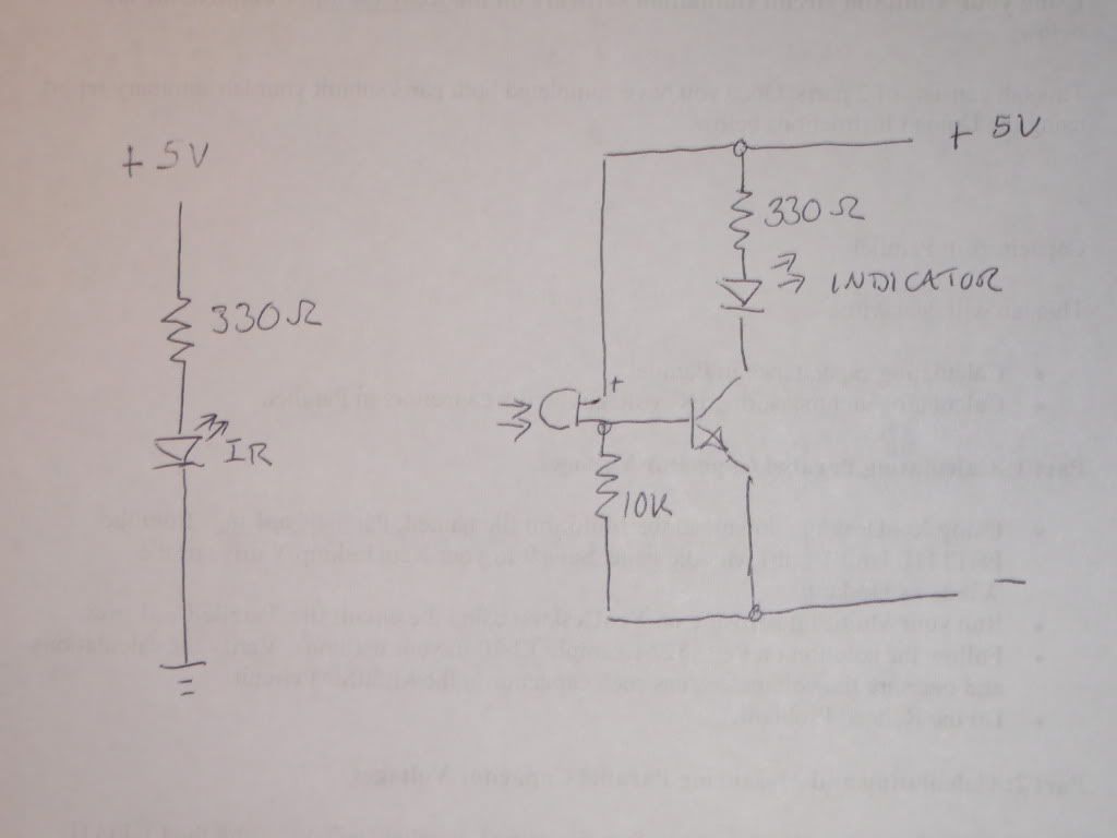
OK, here is the sketch. The transistor can be just about any NPN transistor you can dig up. |
|
February 24, 2011 by leemis |
Thanks, for the help. I finally got it to work! ... Now to play with photoresistors. :) |
Please log in to post a reply.
|
Did you know that Morse code is a compact way to transmit human-readable text over binary channels? Learn more...
|


Copyright © 2013 by NerdKits, L.L.C.