NEW: Learning electronics? Ask your questions on the new Electronics Questions & Answers site hosted by CircuitLab.
Support Forum » How to install the NK bootloader
|
February 19, 2011 by Rick_S 
|
As of late, I've noticed a lot of interest in the programming of the bootloader onto either a new or existing micro-controller. This post is to provide a brief instruction to those venturing into this. Programming a bootloader on a micro-controller requires additional hardware that was not provided with your NerdKit. First and foremost, programming a bootloader requires a different type of programmer. While there are other methods to install a bootloader, for this instruction, I am going to focus on the ISP programmer. An ISP (or In System Programmer) is a device that connects to the SPI port of your micro-controller to program it via a serial protocol. There are several of these devices readily available on the internet, or if you are adventurous, you can attempt to build your own from scratch. Some common ISP programmers include:
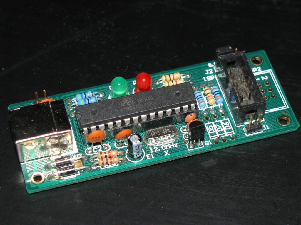
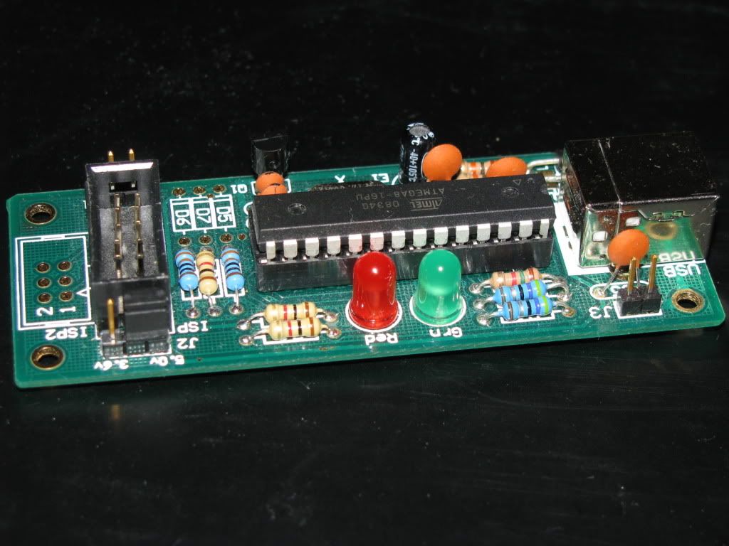
There are others including the popular STK500 dev kit from Atmel, and some other buffered parallel port programmers that can be used. The type you use isn't terribly important. I currently use a programmer I purchased in kit form on ebay. It has the USBASP firmware on it. Here is a photo of the programmer I use. You may be able to find one on ebay, or from the designers WEBSITE.
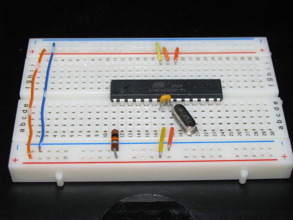
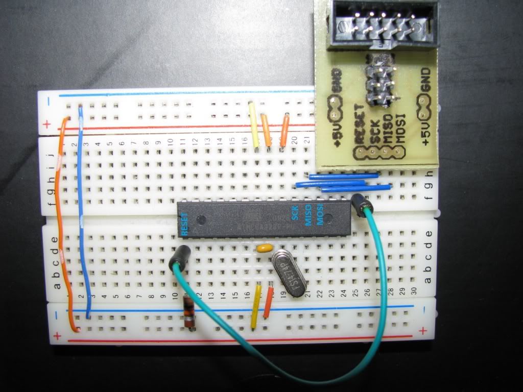
Once you have your programmer, you need to keep a couple of things in mind. Some programmers will supply power to your circuit for programming, some require the circuit to have power. The programmer I am using is capable of supplying the power. As a result, I do not use the power regulator or battery when programming. OK, let's get started. To program the bootloader you will need to build your breadboard very similar to how the initial setup in the guide describes. If your programmer supplies power, you can leave the regulator portion off the board. The main difference is that you MUST replace the jumper wire at pin1 with a resistor (I use 10k). This Photo illustrates the basic setup.
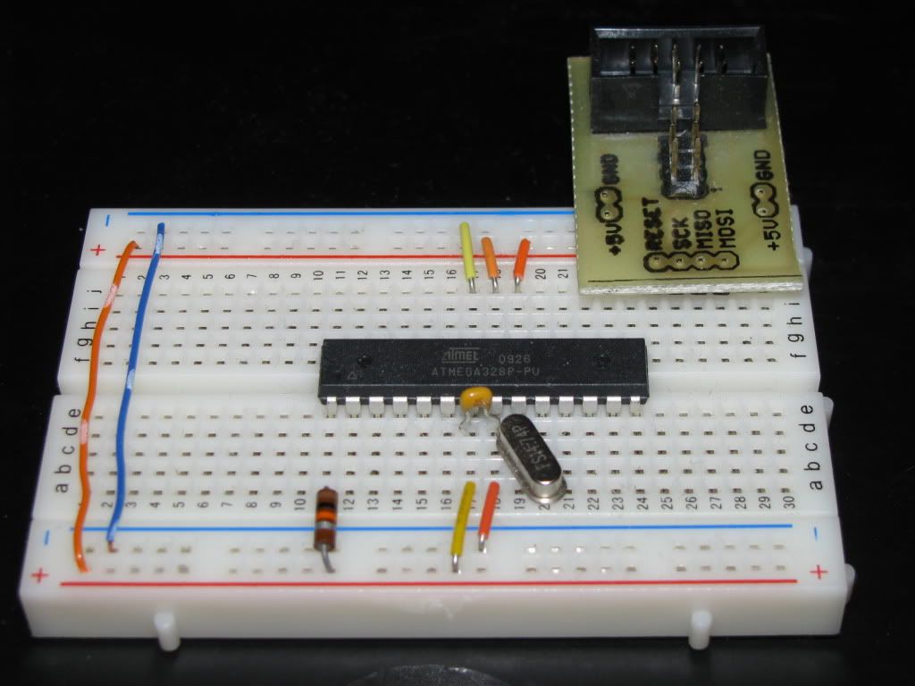
Here I have added a small circuit board I made that breaks out the MOSI, MISO, SCK, and Reset pins from the programming cable to my breadboard. You can purchase similar breakout boards on e-bay, or just attach wires into the ribbon cable connector to the proper places on your breadboard.
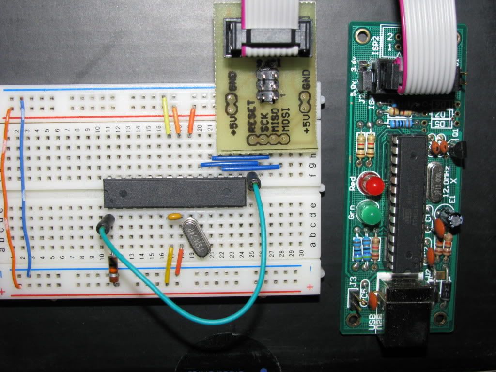
This photo shows the connections to the micro-controller.
And Programmer...
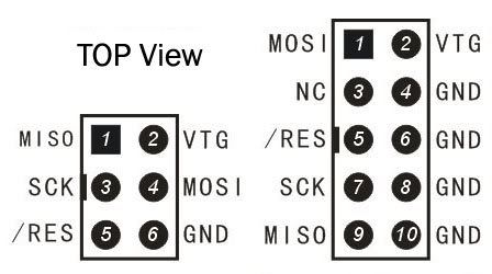
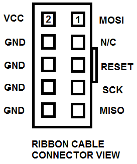
If you go your own route, the pin-out for the connector is this. (This is the header pinout on a board)
Once all your connections are made, you are ready to start loading the bootloader. The NK team kindly has done most all of the work here for you in providing you with a compiled source to upload and a list of all the fuse settings. The main thing here is to make sure to use the proper bootloader for the chip you are programming. The ATMEGA168 and ATMEGA328P are different and used different fuse settings and bootloader file. The chip I am using in my example is the ATMEGA328P. In your code folder you downloaded from the member area, you will find 2 folders for bootloaders. They are called "bootloader168" and bootloader328P) The first thing you need to do is look at the makefile. The default makefile uses a DAPA programmer. You must change this to the type of programmer you have prior to attempting to load the files. In my case, I changed the dapa in the 1st line to usbasp so mine reads like this. Now, just to make sure we start of fresh, it's a good idea to do a chip erase. This will make sure the lock bits are cleared and any existing bootloader/program is cleared off the chip. (It will also test the setup. To do this simply type this from your command line. (substitute your programmer and micro in the proper spots as needed) If your setup is good, you should see this response. If you did, your setup is good, and you are ready to proceed to programming. After you've done the erase, you need to set the fuse bits in the micro to configure it. This is done by navigating into your bootloader folder and typeing: If this was successful, you should see a bunch of lines scroll on your screen as each fuse is programmed. Make sure each section verifies. For the 328P I'm programming, this is what the response is from make. After this is done, you are ready to send the bootloader to the chip. This can be done by typeing: Once you've done this, you should get the following response from make. If you made it to this point, Congratulations!You just installed your bootloader. You should now be able to connect the micro-controller as shown in your guide and use it to upload your programs via the NK programming cable. Rick |
|---|---|
|
February 19, 2011 by JKITSON 
|
THANKS RICK VERY WELL DONE.. JIM |
|
February 19, 2011 by n3ueaEMTP 
|
Rick, this is fantastic, thank you!!! Chris |
|
February 20, 2011 by Rick_S
|
No problem, hope people find it helpful. Rick |
|
March 16, 2011 by Ralphxyz 
|
Man Rick, this is such a great tutorial. It really explains everything step by step. Of course it has failed to work so far but I do not have a good record of things working like they should. I am using the ATmel Dragon programmer (dragon_pp) in HVPP (High Voltage Parallel Programming) mode. The USB fails to be found, I'll keep playing with it and try it on my MAC there I can set a com port. But thanks once again, gee there aught to be a compilation available of all of these user contributed tutorials, you know something like a FAQ maybe. Ralph |
|
March 16, 2011 by Rick_S
|
Thanks for the compliments Ralph. They are appreciated. Why are you doing HVP Programming instead if ISP? Did you really muck one up? Rick |
|
March 16, 2011 by Ralphxyz
|
For some reason I can not get ISP to work, either on the ATmel Dragon or on a ATmel STK600. To load the Bootloader (foodloader.hex) using AVR Studio it is a simple 1- 2 -3 process, So it is easy and I do not have to think about it. In other words I am using HVPP because it works. Setting the fuses in AVR Studio is not for the faint of heart, in fact there are fuse settings in the mike-fusesettings.txt document that you can not set in AVR Studio. Using the "make fuses" would ensure using the same settings. I just have to spend the time to work out why the ISP mode does not work. And to figure out what is happening with the USB detection. I even made a target board to use with the Dragon and STK600 but that also failed in using ISP. I had a unnamed "BETA" ISP programmer (that worked great once I figured out the AVRDUDE syntax to use) but that has never been released or has had limited disclosure. The beta programmer used a Nerdkit ATmel 168 controller as was discussed in a thread we had last month with you and Noter, that essentially described the beta programmer I had received step by step. I tend to try things two or three times and if they do not work and something else does then I just move on and "possible" get back to them at a later date. So sometimes I get back and get things working or sometimes I never get around to it. The ISP problem I get back to every 2 or 3 months and spend a afternoon trying to get it to work. I even asked support@atmel for help describing what was happening and they ended up apologizing for the terrible STK600 documentation, promising to do a complete job in the next release of AVR Studio. They were baffled by my problem. I believe one of the problems with the STK600 is that the contacts have a laquer layer over them that has to be removed. So I tried and could not detect the USB using the dragon I even used -P usb and that just essentially changed the same error message. The Dragon works fine connecting to the usb using hvpp and AVR Studio. Ralph |
|
March 17, 2011 by SpaceGhost |
What an excellent tutorial! Great step by step instruction, this information will surely come in handy for a lot of us. Thank you Rick for your straight-forward, easy to follow instructions. By the way, I've been following your I2C thread also... Very interesting stuff. Kind of a lot to get my head around right now though. I've ordered a few extra MCUs for a project I'm working on - but it's been pretty slow going because free time for me right now seems to be at a premium. But it's great to know that info is here, and that such other really cool stuff keeps showing up. Thanks again Rick for your great contributions! Dave |
|
March 17, 2011 by Rick_S
|
Thanks for the kind words. I'd seen a lot of "how do I install the bootloader" questions and thought I'd put it together. I hope it helps. Rick |
|
March 30, 2011 by lnino 
|
Hi. This is a really great tutorial. I tried to find a circuit board(MOSI, MISO, SCK, and Reset) for my breadboard on ebay like you said. But I had no luck. Where I can get such a thing and what is it called. Maybe I can find it also in europe, to have less waiting time because of the delivery. Thanks. |
|
March 30, 2011 by Rick_S
|
I made my own, but ebay does have them. Here is a quick link to one I found. Rick |
|
March 30, 2011 by lnino
|
Hi Rick, thanks for you reply. I will search a little through the internet if I can find a part which is not that close to Japan. :-) |
|
April 01, 2011 by lnino
|
Hi back again. can I flash every atmega168 with NK Booatloader for 168? There are different types of atmega168. + atmega168-20pu + atmega168-20au . .. Is there a difference? Or can I flash all of them? |
|
April 01, 2011 by Rick_S
|
You should be able to flash any of them as long as they are connected correctly. The different suffixes are for different speed and package styles. Rick |
|
April 01, 2011 by lnino
|
Hi Rick, thanks for the reply. |
|
April 03, 2011 by lnino
|
Hi Rick, on the link of the designers website I saw the part USBasp. HERE Is this the same thing? Is this also for flashing the bootloader on my MCU? The USBasp would be closer to buy for me, because it is from germany. The delivery from the states takes 4-5 weeks in the most cases. And I can't wait. smile |
|
April 09, 2011 by Rick_S
|
Yes, that will do the exact same thing.... Sorry I missed your post several days ago. I have the USBASP firmware on my device so functionally they are identical. Rick |
|
May 04, 2011 by Singlecoilx3 
|
If you are having trouble installing the drivers in Vista or Win7 (as I did) because of unsigned driver problems follow these steps in the post by 'knandan' on AVRFreaks. |
|
May 05, 2011 by Singlecoilx3
|
can you explain/show the connections more for us folks that don't have that breakout board? I was able to get the driver installed and working but when i try to run: avrdude -c usbasp -p m328p -e I get the response: avrdude: error: could not find USB device "USBasp" with vid=0x16c0 pid=0x5dc I also tried using AVR Studio as was mentioned on fun4diy but I get a similar error saying: Unable to connect to tool AVRISP mkII (00A20000011E0) and then: Failed to get interface clock value. Thanks!! |
|
May 05, 2011 by Rick_S
|
The kit he sells for the programmer comes by default with an AVRISP MkII compatable firmware. At the time I bought mine, he had a note on his site saying that some people had experienced problems with that firmware in Win Vista and 7 and suggested the USBASP firmware as an alternative. That is the firmware I am running. If you didn't request USBASP firmware when you ordered, you will have to change the lines that reference it for avrdude. So anywhere you see usbasp in my instruction, replace that with avrispmkII. When you assembled your 10 pin cable, did you check the orientation of the keyed side? If you assembled it properly, with the keyed side up, the red stripe on the wire would be to the left of the connector like this.
(Sorry for the crappy cell phone pic) If you did make it this way, the pins would be labled as such:
See the datasheet for the pin labels on the chip. One other thing. The programmer can supply power to your target chip for programming but that can be iffy. I usually remove the power jumper so the target chip power is disconnected from the porammer then power the chip with it's own power supply. Rick |
|
May 05, 2011 by Singlecoilx3
|
thanks for the quick reply Rick, now i am getting: avrdude: ser_open(): can't open device "com1": the system cannot find the file specified. Thanks |
|
May 05, 2011 by Rick_S
|
Try entering this at the command line and see what happens. You may need to tell AVRdude that it is on usb not serial. The -P USB does this. If this works, add that to your AVRDUDEFLAGS line in the makefile. Rick |
|
May 05, 2011 by Singlecoilx3
|
I am still not able to get anything working. I have it double checked the wiring, the AVR MKII board, tried typing everything you suggested, tried changing the makefile as you suggested. I keep getting shut down. I am pretty good at troubleshooting problems when I understand how things work but I am clueless about all this stuff. Something isn't right because even AVR Studio says it can't even connect to the AVR MKII board. Lost in the universe somewhere, Eric (Singlecoilx3) |
|
May 06, 2011 by Singlecoilx3
|
Here is my setup-
|
|
May 06, 2011 by Singlecoilx3
|
|
|
May 06, 2011 by Singlecoilx3
|
|
|
May 06, 2011 by Rick_S
|
The only difference I see in your wiring, would be that you have AVREF (Pin21) to ground instead of VCC as I do. I don't think that would make a difference in programming the chip though. The error you are getting however seems to be a problem with AVR Studio talking to the programmer. I know that Atmel has updated the firmware in their True AVRISP MKII programmers to support newer xmega chips. Also, the firmware the fun4diy guy uses (if you follow the link) to emulate an AVRISP MKII isn't even supported anymore by the author. Maybe (and this is only a guess), the version of AVR Studio you are using knows that isn't a real AVRISP programmer and is having trouble communicating through it. Did you try AVRdude again? What were it's responses? One other thing you could try, remove the power jumper (the one labeled 5v...3v) and power the target micro with it's own power. Rick |
|
May 06, 2011 by Ralphxyz
|
Wow thanks Singlecoilx3, I didn't know ATmel had released AVR Studio 5. Try installing AVR Studio 4, you might have better results. Ralph |
|
May 06, 2011 by Singlecoilx3
|
@Rick, Thanks for catching the vcc/gnd wiring error. I will change that when I get home. To answer your other question- I did try AVRdude again, but will give it another try after fixing the wiring issue you pointed out. @Ralph, I will give AVR Studio 4 a try also. Thanks guys. This issue has really gotten me frustrated :-| Eric |
|
May 06, 2011 by BobaMosfet 
|
I've got AVR Studio 4 on Windows 7, and it works fine. I didn't know AVR Studio 5 was out yet. BM |
|
May 06, 2011 by Noter 
|
AREF is only used by the ADC so it doesn't matter if it goes to GND or Vcc or has no connection when the ADC is not in use. I don't see how it could make any difference as far as programming the chip via SPI. AVRDUDE will give a message something like "Found programmer: Id = "AVRISP "; type = S" if it is communicating with the programmer. No point in worrying about wiring in the target circuit until you know you have good contact with the programmer. Once that happens and there is a problem in the wiring I think you'll get timeout errors from AVRDUDE. I haven't used AVR studio but I would think there would be something similar, a way to verify communication with the programmer. Maybe you can query the programmer for version info and type or something without attempting a download at the same time? |
|
May 06, 2011 by Noter
|
By the way, if your target chip is brand new, you'll need the low speed jumper installed or other method of setting low speed for the SPI on your programmer because the new chip is set at the factory to run at 1mhz. |
|
May 06, 2011 by Rick_S
|
I've sent an e-mail to the fun4diy person to see if I can get a copy of the firmware he uses by default on the programmers. If he sends it to me I'll load it up on a chip and test things out with my programmer. Maybe I can figure it out then. Clicking on the link fun4diy has to the original firmware authors site, I find a somewhat dis-organized site and I'm not sure what to get if the original author even has the same firmware any more. Hopefully the fun4diy guy will get me a copy of what he uses. Have you built your second programmer yet? I know you said you purchased two. If not, I could possibly program up a mega8 with the USBASP firmware and send it to you if we can't figure this one out. Rick |
|
May 06, 2011 by Singlecoilx3
|
@Noter thank you for the helpful info. This will surely save me some headaches once I get to that point. Much appreciated. @Rick that sounds great. Thank you for the incredible support thus far. I will try what you have mentioned tonight and if I have no luck I will build up the 2nd programmer to try it instead. As frustrating as this thing is I'm sure I am going to understand it better once it is bsorted out than if it just worked the first time :) Also Rick, I have a spam email account that I can post here on the forum that I don't care if it gets spidered by harvester bots. I never check it on my own but if you tell me you have sent something I will take a look: namfoo82#at#yahoo.com Once you email me there I will reply to your email with the one I normally use so you have it. |
|
May 06, 2011 by Rick_S
|
If you build the second programmer, make sure to socket the microcontroller, that way if you want to swap it for another, you can keep the original the way it is... Also makes it easier to repair if something goes bad that damages the micro. Rick |
|
May 06, 2011 by Rick_S
|
I just got a reply from the fun4diy person. He sent me the default programmer firmware. If I have time tonight, I'll load it up on my programmer and see if I can replicate your problems. |
|
May 06, 2011 by Singlecoilx3
|
I was able to pick up an IC socket to use for the 2nd programmer. I will make sure to use that when I build the 2nd one tonight. Thanks again for your help Rick |
|
May 07, 2011 by hariharan 
|
Hi guys, I bought the kit and assembled it, but now, i am stuck with the driver. I really didn't understand which driver i should download. |
|
May 07, 2011 by Rick_S
|
Hariharan, which kit are you referring to? Singlecoilx3, I instlled the avrisp mkII firmware but could never get it to work. It shows up, but has an exclamation point saying it could not start. I tried libusb but didn't get it to work either. One thing though, I think AVRStudio uses the Jungo USB drivers so if it isn't listed there as working that may be why you aren't getting the desired results. I really wish I could go up and add to my original instruction... IF you buy one of these programmers, get them with the usbasp firmware... I know that works and works well with avrdude. Singlecoilx3, I've sent an e-mail to the account you listed. Rick |
|
May 07, 2011 by Singlecoilx3
|
update#1- built the 2nd programmer, chip is socketed. currently installing avr studio 4 to give that a try also. I sent you an email reply from my real email address Rick. I am going to order another kit from that guy with the USBasp FW instead and give that a try. |
|
May 08, 2011 by Rick_S
|
The current version of this instruction is located in the newly released NerdKit LibraryRick |
|
May 08, 2011 by hariharan
|
i mean the USBasp kit which you (Rick) were refering in the first place. I bought the USBasp fw one. |
|
May 08, 2011 by Rick_S
|
The Driver can be found on the official USBASP site. Here is a LINK directly to the driver there. Rick |
|
May 08, 2011 by hariharan
|
Thanks Rick!!! But when i tried downloading the driver,nothing seems to happen. Will this work on Vista? |
|
May 08, 2011 by Rick_S
|
Yes, I use mine on both Win7 and Vista machines with no problem. Rick |
|
May 08, 2011 by Singlecoilx3
|
I can get access to an XP machine... I have the AVR ISPMKII programmer... should these work together? What do I need to do? Eric |
|
May 08, 2011 by Singlecoilx3
|
nvm, the person I was going to borrow the computer from thought they had XP but it was actually Vista. :( |
|
May 08, 2011 by Rick_S
|
If you could get access to an XP machine, just load AVR Studio 4. According to Mengjin Su (the guy from fun4diy), That shoud be all you need. Rick |
|
May 08, 2011 by Singlecoilx3
|
hmmm.... the word Linux just popped into my head... Wondering if it would be worth my time........ |
|
May 08, 2011 by Noter
|
How about virtual XP on your Win7 machine? Maybe it would work for AVR Studio 4 and the AVR ISPMKII programmer. |
|
May 08, 2011 by Singlecoilx3
|
UGood thinking. I tried to do that earllier today, but sadly M$oft doesn't allow it with home premium edition of win7. My work computer is xp though... wink |
|
May 08, 2011 by Noter
|
Did you download and try it? Here's an article that says it will work on home editions and provides direct links for download. Windows 7 Virtual PC and Windows XP Mode Official Direct Download Links |
|
May 08, 2011 by Singlecoilx3
|
Link Yea I tried it and it does not work in home premium by design. I did just find this link though here. I don't have a copy of xp with a cd key anymore so I will just try it at work tomorrow on the xp machine or wait for my new programmer kit with usbasp to arrive. |
|
May 08, 2011 by Singlecoilx3
|
Thanks for the good suggestion though :) |
|
May 09, 2011 by Singlecoilx3
|
when I type: I get: this is what is in the file 'bootloader': |
|
May 09, 2011 by Singlecoilx3
|
^^ this is on the XP machine at work |
|
May 09, 2011 by Singlecoilx3
|
...as a test I typed that without the usb cable even plugged in and got the same response. also avr studio 4 doesn't recognize it. what drivers/etc should I have installed? |
|
May 09, 2011 by Rick_S
|
Eric, I wasn't sure of the driver issue either since I had not used that firmware. That was one of the questions I asked Mengjin. Here is a cut and paste of my question and his response: From his response, I have to make the assumption that the driver should load as part of AVR Studio. However based on what you have said, it seems otherwise. Are you sure you don't want me to do what I stated in my email? Rick |
|
May 09, 2011 by Singlecoilx3
|
Re: Rick- I think I have exhausted my patience with trying to get this FW to work on any OS. I did order another kit with the FW you recommended and it was shipped out on SAT. I should get it by tomorrow since the city Mengjin sends them from is only about a 2 hour drive from where I live. I will pick up again with the new FW as soon as I get it. I certainly appreciate what you offered but it will not be necessary. :) I can't thank you enough for all the help you have given me on this issue. You truly are a key player in making this such a great community. Eric |
|
May 09, 2011 by Rick_S
|
Thank you for the kind comments. I do feel somewhat responsible and wish I could have gotten it to work. I know the USBASP firmware works fine on my Win7 machine so I'm sure you'll have no problem with it. Rick |
|
May 09, 2011 by Singlecoilx3
|
I thought there may have been a possibility you felt somewhat responsible. That is exactly why I decided not to take you up on your offer :). Definitely not your fault, and I learn something every time things don't go as I expected. You did also mention it somewhere in the original writeup but I scanned it hastily and didn't pay attention to the details :-/ I am excited to get the programmer with the other FW and get it going and move on to the next part of my Higher Resolution Large LED Display project. <--- totally just plugged it in your thread :> :> :> |
|
May 10, 2011 by Singlecoilx3
|
got the new kit tonight with the USBASP firmware on it. still having problems :( I type: and get: the red light comes on when I type the command, but quickly goes out again. I also tried AVR Studio 4 and it says 'failed to connect' when I choose AVR ISPMKII and USB. This is truly bad luck I am having... :( |
|
May 10, 2011 by Singlecoilx3
|
ZOMG!!111!!!! it did something! I replaced the ribbon cable which must have been bad. it erased the chip :) :) :) woot!!111! |
|
May 11, 2011 by Ralphxyz
|
Ok, so now I hope we can get some work out of you. We do have a wedding coming. Ralph |
|
May 11, 2011 by Singlecoilx3
|
Haha :) We most certainly do! I did end up getting one of them all programmed last night before I passed out for the night. I'll finish the programming them with the bootloaders tonight and then it is time to move on to something different :) |
|
January 16, 2012 by lnino
|
Hi, after some time passed by, I found some time to continue programming on my MCU. I have bought the USBasp and tried to use this tutorial to flash my atmega168. But it won't work. Do you have some ideas where the problem could be? Here are some screenshots. As I have seen there is no current on the red line on my breadboard. Is this okay?
|
|
January 16, 2012 by Rick_S
|
Not all USPASP devices provide power for the target device. You need to find out if yours does. The programmer I pictured above has the ability to provide power via a jumper next to the 10 pin header. It can provide 5v, 3.3v, or no power (with the jumper removed.) You may have to add a jumper for your device. Where did you get your USBASP from? Rick |
|
January 16, 2012 by Rick_S
|
After reading the label on your programmer, I see it is the official one. Make sure your jumper for applying power to the target and the low speed jumper are both in place. That should make it work if all is wired correctly. Rick |
|
January 17, 2012 by lnino
|
Hi Rick, thank you for your reply. Regarding to this schematic of my USBasp, would be JP1 and JP3 the both jumpers which I have to set? But as I can see the jumper are not in place on my USBasp, I think I have to solder them. :-)
|
|
January 17, 2012 by Rick_S
|
Yes, to provide target voltage from your programmer and program the bootloader on a new mcu, you would need both. (Actually, I think you can get away without the slow speed jumper as long as the USBASP firmware is the latest. I believe you pass the baud parameter to it and it will control the speed. The jumper is just and easy hardware method to control this. Rick |
|
January 17, 2012 by lnino
|
Hi Rick, I have now soldered the jumper pins on my USBasp. After setting the both jumpers I have now current on the "red line" on the breadboard. But when I enter the command: "avrdude -c usbasp -pm168 -e" the failure above still occurs. Here some detailed fotos of my wiring. Maybe you have a suggestion.
|
|
January 17, 2012 by lnino
|
EDIT: Now it worked. The wires were connected the wrong way. It took some time to understand that the pin order changes when I plug in the male in the female. Now the failure is gone. I will forward now to get my controller flashed. :-) |
|
January 17, 2012 by Rick_S
|
I thought one of the people earlier in this thread might have had that issue, that was why I posted the picture of what the cable end pinout would be. Glad you got it going, let me know how it works for you! Rick |
|
January 18, 2012 by lnino
|
Hi Rick, yes The view of The Ribbon cable was The Solution. Thanks for The Tutorial. After wiring it The right Way i could follow your Tutorial and it worked Great. Thanks a Lot. |
|
January 18, 2012 by lnino
|
Hi Rick, yes The view of The Ribbon cable was The Solution. Thanks for The Tutorial. After wiring it The right Way i could follow your Tutorial and it worked Great. Thanks a Lot. |
|
January 18, 2012 by Rick_S
|
Good to hear you got it programmed. Rick |
|
October 12, 2014 by jlaskowski |
I'm using an AVR mkII and it says it does not supply power. Does that mean I need to just keep pin one connected to +5V and use neither the resistor nor jumper? |
|
October 12, 2014 by jlaskowski |
In answer to my own post above, I included the 10k resistor between pin 1 and +5V and connected reset from the avrisp mkII to pin 1. When reading the documentation that comes with the AVRISP mkII, it says you must install the AVR USB driver. It turns out that does not work with avrdude (it may have at one time, but doesn't now, since Atmel switched to the Jungo USB driver). Instead, I had to download the libusb drivers as shown here. I followed the instructions in that link and it didn't install the driver properly. I rebooted my machine, tried again and it worked the second time. Before I realized the driver was incorrect, I tried installing a newer version of avrdude.exe and avrdude.conf (as opposed to the ones that come with WinAVR-20090313). Once I changed the driver (as mentioned above), I ran "make fuses" and it executed "avrdude ${AVRDUDEFLAGS} -U lock:w:0x2f:m" fine, but then failed on "avrdude ${AVRDUDEFLAGS} -U efuse:w:0x05:m", saying, "did not find any USB device 'usb'." I reverted back to the older avrdude.exe and avrdude.conf files and it worked fine. |
|
August 16, 2015 by edSky |
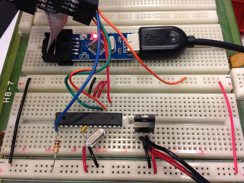
What a day! I purchased a USBasp programmer on ebay and it came with a 10-pin to 6-pin adapter. Everything I needed. I installed the latest driver I could find that worked with Windows 7 - usbasp-windriver.2011-05-28.zip - and got it working after googling around. Next got a few tubes of ATMEGA168 and ATMEGA328P chips from Mouser Electronics. Then I dug up my old Heathkit H-8 prototyping board (yeah, I know) and wired everything up as outlined above. I tried dozens of times and kept getting "target doesn't answer" errors. I cried. Next I downloaded a neat GUI tool, eXtreme Burner AVR. That too, failed. I hoped I would see more information than avrdude shows but I didn't. I googled some more, looked up more and more about programmers and finally tried something. In the images and tutorial above only the MISO, MOSI, ReSeT and SCK are connected to the ATmega. I took a chance and connected the programmer's GND to the ATmega's ground and voila! I was able to successfully erase the chip!
Next step, the bootloader and then more fun. Thanks for keeping this site alive! |
|
August 16, 2015 by JKITSON
|
Nice job. Nothing like a lot of goodies, nothing works, cry a little and WOW it works. Those are the best of times.... Good luck & have fun.. Jim |
|
August 16, 2015 by edSky |
Completing the two circuits via ground did the trick. The crying part was just poetic license (although I was snappy for a bit when my wife popped in to work to say "Hi!"). The programmer I got was AVR 10 Pin USB Programmer 3.3V/5V 51 ATMEGA8 w/ Cable & adapter USBasp USBISP In the meantime I've met my goal of creating four backup ATmega168's this afternoon. My next anxiety is what to do if the PL2303 programming header dies or gets lost. Until then, this was very helpful |
|
August 17, 2015 by Rick_S
|
Glad to see the old thread still helps out some. I'm also glad to see you figured out that the ground being connected was important. In my write-up, I made the assumption that all the connections shown in the breakout would be made but only specified the MOSI, MISO, SCK, and Reset mainly because those were the signals broken out on my little breakout board, however the power (5V & GND) were also broken out I just didn't mention them. I guess I should have as it would have saved you some tears As for worrying about your PL2303 USB-Serial adapter, don't. Now that you have an ISP programmer, you don't even technically need it. You can fully program the chips with it instead. But, if you prefer the USB-Serial method, most USB-Serial adapters will work as a replacement if something were to go wrong with your original. Rick |
|
August 17, 2015 by edSky |
Rick, If I were to use the ISP programmer instead of the PL2303 how should I wire it up? The same as with programming the bootloader or differently? And what changes, if any, would I need to make to the makefile? Thanks in advance! Ed |
|
August 18, 2015 by Rick_S
|
The wiring would be the same as for installing the bootloader. The changes to the makefile would be the same changes you made to the bootloader makefile except instead of replacing the dapa line it would be the avr109 line with the line from above. For example, this line: would become The advantage to using the ISP programming method is that now all available space on the micro-controller can be utilized since you no longer need a bootloader, it's also quicker. Just be sure not to mess around with the fuses on the chip - specifically the fuse for changing the reset to a data pin. Doing this will prevent you from being able to reprogram the chip with ISP and if you have no bootloader, that way as well. The only way to get back from that is with a High Voltage programmer. Noter has built one of those and used it successfully on some of his projects. Serial through a bootloader is slightly slower, but it is safer for the novice. That's why arduino uses a serial bootloader. Rick |
|
October 26, 2016 by MikeHI |
To: edSky, would you be willing to sell me Atmega168 with Nerdkits bootloader on it so I can replace my bad ATmega168? Don't know if I am capable of going through all the above post on building my own bootloader. |
|
October 27, 2016 by jlaskowski |
Would you be willing to do a 328 instead of a 168? I'm set up to load on 328 at the moment and I can sell you one for $10. If so, contact me at jim_laskowski@yahoo.com with your address. |
|
October 27, 2016 by scootergarrett 
|
This brings up a good point, in the event of a flood (for example) I could loose all my bootloaded MCUs which I use to bootload fresh chips .Then I would have no way to bootload a fresh chip with the Nerdkits. I'm going to put a bootloader chip and a good raspberry pi in a safe place, in case of the apocalypse that my be 2 weeks away (just kidding lets keep politics as far from the logic of micro controller as we can) |
Please log in to post a reply.
|
Did you know that two resistors plus a transistor can be used to make a better voltage supply? Learn more...
|


Copyright © 2013 by NerdKits, L.L.C.