NEW: Learning electronics? Ask your questions on the new Electronics Questions & Answers site hosted by CircuitLab.
Microcontroller Programming » Reading a simple digital input
|
April 09, 2009 by hevans (NerdKits Staff) 
|
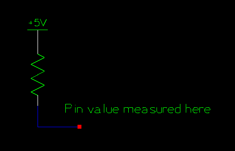
To many microcontrollers are interesting because they can serve as a bridge between the digital software world and the "real" world. One of the most basic things (and unfortunately often overlooked) thing you might wish to do is simply read a digital input, possibly from a simple pushbutton or switch. In this quick example I will explain how to read a very simple digital input. The first step is to set the pin to input mode, this is done by setting the DDRX register of the pin you want to use to a value of 0. Putting a pin in input mode means that the MCU is not driving the pin, and reading its value. So assuming my switch is connected to PC0, we want to set Then, we want to turn on the internal pull-up resistor for that particular pin: Turning on the pull-up resistor will allow us to do only half the work with our switch. When the pull-up resistor gets turned on it connects the pin in series with the pullup resistor to the positive supply of the MCU. You can see from the diagram that this resistor will "pull-up" the voltage of the pin to the +5 supply of the MCU (a logically high voltage).
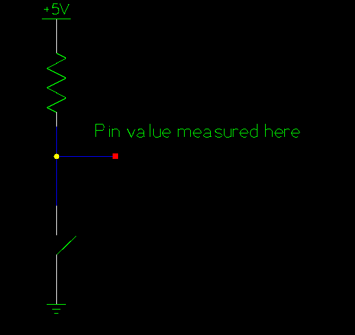
Now lets go ahead and put our switch into the circuit. We connect our switch in series with the pin and GND. Now we have the option of closing the switch, which will connect the pin to GND and pulling its value down to a low voltage. When the switch is opened, the pull-up resistor is able to pull the value of the pin up to 5V again.
Now that we have the circuit all hooked up, we can worry about reading the value of the pin in software. To read the value of a pin we must read the value of the PINX register. This case we want to read the value of PC0 of the PINC register. In order to do that we must mask out the bits we are not interested out of the PINC register: The PCO spot in PINC will be 1 if the pin has a high voltage on it, and 0 if the pin is at a low voltage. Notice in the line above how the value variable will be set to either 0, if pin was low, or some number if the pin was high. From here on in the code you can use the value variable to do things conditionally on whether your switch was open or closed. Note that in C any number that is non-zero is "true" so as long as any of the bits in the value variable are 1 the if part of the conditional will execute. I hope this is useful. If there are any questions go ahead and reply to this thread and I will do my best to answer them. If you have something to add to my explanation go ahead and post that too! |
|---|---|
|
April 09, 2009 by seanmcpherson |
Okay, silly Q, then. What would be the maximum number of digital inputs we can monitor with the basic kit? I'm always dealing with stuff that'll open or close a contact for me when <x> event happens, and I'd love to poke at it with my kit :) |
|
April 09, 2009 by hevans (NerdKits Staff)
|
Good question Sean. That depends on a couple of things. Technically, the Atmeaga168 has the capability to read 23 digital inputs, pretty much all the pins that are not power and ground. However, we can't use all of them with our setup. Because we are using an external crystal pins 7 and 8 get used right off the bat. The reset pin takes up PIN 1, and the programming switch takes up PIN 14. So from the original 23 we are down 4 for a total of 19 if you are willing to run the NerdKit completely bare-bones without using the serial cable, or having the LCD hooked up. If you want to be able to send data back to a PC over the serial port from your MCU that takes up PINs 2 and 3, and if you want the LCD that takes up the remaining 6 pins on the left side. So even with the NerdKit fully hooked up the LCD and Serial cable, you still have the 11 pins on the right side of the MCU available to use as a digital input (or possibly output) pins. If you notice on page 31 of the NerdKits Guide (you can download the updated version from the downloads section) there is a neat diagram of which pins are used when the NerdKit hooked up and you can see that the LCD, serial cable, crystal, and other necessary connections fill up the left side. If you check out the LED Marquee project you can see an example where we did not use the LCD and used the 17 available pins as digital output pins. Sorry for the overly verbose explanation to an otherwise simple question =) Humberto |
|
April 09, 2009 by seanmcpherson |
Humberto, Not overly verbose at all. Reading thru the data sheets and such is what made me realize I was having trouble determining how many simple contact closures I could test against :) Ultimately, it looks very much as if with a few simple steps we'll have just built a very simple home security/monitoring system to identify when doors and windows open, when a sump pump kicks on, etc. Thanks! |
|
April 09, 2009 by wayward 
|
Sean, you may want to get some multiplexers and shift registers if you need more inputs/outputs! These are extremely simple to use. I bought a bag of TTL 7400 series integrated circuits for a few dollars and got a fair amount of logic gates, multiplexers, demultiplexers, counters, buffers, etc. They are all documented thoroughly and playing with them is loads of fun! |
|
April 18, 2009 by mrobbins (NerdKits Staff) 
|
Sean, If you don't care about reading all of your digital open/close circuits at the exact same microsecond, be aware that you can use a matrix-type technique to vastly increase the number of inputs that you can read. Just as the LED Marquee project uses row-column addressing to control 120 LEDs with just 17 digital input/outputs, you can modify that concept a bit to work with open/closed switches instead of LEDs. Might help if you need a lot of switch/button inputs! wayward, Interesting idea... if we were to put together a little TTL/CMOS logic IC "grab bag", do you have specific chips in mind that you think would be useful for lots of people? Mike |
|
April 26, 2009 by Ethanal |
What is a pull-up resistor and what is it's use in this circuit? |
|
April 26, 2009 by mcai8sh4 
|
Since this is all new to me, I'm not the beat person to answer your questions, but I may be able to help shed a little light on it. The way I see it, the pull up resistor gives the pin a +5V, but is only a very weak resistance. Then then the switch is closed to ground the pins voltage is then zeroed (maybe?). This way you can tell if a switch is open or closed. I'm sure someone will correct me, but that's the way I see it. |
|
April 26, 2009 by hevans (NerdKits Staff)
|
Ethanal, A pull-up resistor is actually a relatively high resistance. If you look at the Datasheet on p304, Rpu is between 30 and 50K ohms. as the name suggests, the purpose of this resistor is to pull the voltage up to 5V when the switch is open, and allow us to close the switch without shoring the power supply up to ground. Think of it this way. what would happen if I did not have the pull-up resistor there, and I closed the switch. There is a drop from 5V to 0V and practically no resistance between them. Sine V=IR, the voltage drop is 5, but R is very very small, this means that I (the current) is really high. That amount of current can't be sourced by the microcontroller so you just won't be able to really pull that voltage down to 0. Now put the pullup resistor in. With the switch open, the output is still +5 because no current flows through the resistor. When the switch is closed, there is a 5V drop across the resistor but this time R is more than 30K ohm, this means that I is a little more than .15 milliamps (which is perfectly acceptable). Let me know if this makes sense. Humberto |
|
April 28, 2009 by jermiy |
Hey there I was trying to program this microcontroller for multi-tasking, well besically i was trying to read fron three digital sensors and use those values to certain things, the firast sensor is the ultrasonic, which measures the distance and output that value to the servo motor, so that it will stop once it recognises any object with some distance value, the second and the third sensors are for reading the light sensitivity and controll the wheel so my car can fallow the line, but for some reason i couldn't use two sensors at the same time, the rear motor is working and does waht i wanted to do but the front wheel motor does not work at all, I tasted it with oscilloscope if it has an output but it doesn't have any thing, well i used two values for the top and low values for my PWM but i couln't figure it out why i'm not getting output on PB1, i attached the code, so please any one help me so i can make it to work. define F_CPU 14745600include <stdio.h>define F_CPU 14745600include <stdio.h>include <avr/io.h>include <avr/interrupt.h>include <avr/pgmspace.h>include <inttypes.h>include "../libnerdkits/delay.h"include "../libnerdkits/lcd.h"include "../libnerdkits/uart.h"//#include <avr/sfr_defs.h> //#include <inttypes.h> //#include "ping.h" include "servo.h"define ULTRA_SONIC_MASK (1<<4)define ULTRA_SONIC_OUT (DDRB|=ULTRA_SONIC_MASK)define ULTRA_SONIC_IN (DDRB&=~ULTRA_SONIC_MASK)define ULTRA_SONIC_SET (PORTB|=ULTRA_SONIC_MASK)define ULTRA_SONIC_RESET (PORTB&=~ULTRA_SONIC_MASK)define ULTRA_SONIC_IS_LOW (!(PINB&ULTRA_SONIC_MASK))define ULTRA_SONIC_IS_HIGH ((PINB&ULTRA_SONIC_MASK)==ULTRA_SONIC_MASK)define ULTRA_SONIC_MASK_RIGHT (1<<3)//#define ULTRA_SONIC_OUT (DDRB|=ULTRA_SONIC_MASK) define ULTRA_SONIC_IN_RIGHT (DDRB&=~ULTRA_SONIC_MASK_RIGHT)define ULTRA_SONIC_SET_RIGHT (PORTB|=ULTRA_SONIC_MASK_RIGHT)define ULTRA_SONIC_RESET_RIGHT (PORTB&=~ULTRA_SONIC_MASK_RIGHT)define ULTRA_SONIC_IS_LOW_RIGHT (!(PINB&ULTRA_SONIC_MASK_RIGHT))define ULTRA_SONIC_IS_HIGH_RIGHT ((PINB&ULTRA_SONIC_MASK_RIGHT)==ULTRA_SONIC_MASK_RIGHT)define ULTRA_SONIC_MASK_LEFT (1<<5)//#define ULTRA_SONIC_OUT (DDRB|=ULTRA_SONIC_MASK) define ULTRA_SONIC_IN_LEFT (DDRB&=~ULTRA_SONIC_MASK_LEFT)define ULTRA_SONIC_SET_LEFT (PORTB|=ULTRA_SONIC_MASK_LEFT)define ULTRA_SONIC_RESET_LEFT (PORTB&=~ULTRA_SONIC_MASK_LEFT)define ULTRA_SONIC_IS_LOW_LEFT (!(PINB&ULTRA_SONIC_MASK_LEFT))define ULTRA_SONIC_IS_HIGH_LEFT ((PINB&ULTRA_SONIC_MASK_LEFT)==ULTRA_SONIC_MASK_LEFT)uint16_t ultra_sonic (void) { uint16_t fcap=0,scap=0; ULTRA_SONIC_OUT; ULTRA_SONIC_SET; delay_ms(30); ULTRA_SONIC_RESET; ULTRA_SONIC_IN; //TCNT1=0; while(ULTRA_SONIC_IS_LOW); fcap=TCNT1; while(ULTRA_SONIC_IS_HIGH); scap=TCNT1; return scap-fcap; } uint16_t ultra_sonic_left (void) { uint16_t lfcap=0,lscap=0; //ULTRA_SONIC_OUT; ULTRA_SONIC_SET_LEFT; delay_ms(50); ULTRA_SONIC_RESET_LEFT; ULTRA_SONIC_IN_LEFT; //TCNT1=0; while(ULTRA_SONIC_IS_LOW_LEFT); lfcap=TCNT1; while(ULTRA_SONIC_IS_HIGH_LEFT); lscap=TCNT1; return lscap-lfcap; } uint16_t ultra_sonic_right (void) { uint16_t rfcap=0,rscap=0; //ULTRA_SONIC_OUT; ULTRA_SONIC_SET_RIGHT; delay_ms(50); ULTRA_SONIC_RESET_RIGHT; ULTRA_SONIC_IN_RIGHT; //TCNT1=0; while(ULTRA_SONIC_IS_LOW_RIGHT); rfcap=TCNT1; while(ULTRA_SONIC_IS_HIGH_RIGHT); rscap=TCNT1; return rscap-rfcap; } int main() { TCNT1=0; lcd_init(); FILE lcd_stream = FDEV_SETUP_STREAM(lcd_putchar, 0, _FDEV_SETUP_WRITE); lcd_write_string(PSTR(" Wheel controller ")); // set PB2,PB5 as output //DDRB |= (1<<PB2) | (1<<PB5); DDRB |= (1<<PB1) | (1<<PB2);// | (1<<PB3); //DDRB |= (1<<PB5); // wheel motor outs //DDRB &= ~(1<<PB1); // set PB3 as input sensing line //DDRB &= ~(1<<PB3); // set PB5 as input sensing line // init PWM pwm_init(); } and the servo is this void pwm_set(uint16_t x) { OCR1B = x; } void pwm_steering_set(uint16_t y) { OCR1A = y; } define PWM_MIN 2764.8define PWM_MAX 2975define PWM_NEW 2000define PWM_START 2765define PWM_0 2865define PWM_1 2855define PWM_2 2615define PWM_3 2845define PWM_4 2830define PWM_5 2790define PWM_6 2680define PWM_7 2680define PWM_LEFT 1843.2define PWM_RIGHT 3686.4define PWM_STRAIGHT 2764.8void pwm_init() { // setup Timer1 for Fast PWM mode, 16-bit // COM1B1 -- for non-inverting output // WGM13, WGM12, WGM11, WGM10 -- for Fast PWM with OCR1A as TOP value // CS11 -- for CLK/8 prescaling ICR1 = 36864; // sets PWM to repeat pulse every 20.0ms
pwm_set(PWM_START);
pwm_steering_set(PWM_STRAIGHT); // each count is 8/14745600 = 0.5425us. // so 1.0ms = 1843.2 // 1.5ms = 2764.8 // 2.0ms = 3686.4 // 20.0ms = 36864 } |
|
May 10, 2009 by Ethanal |
Yes, it makes sense. So basically, it gets the 5v down to 0? Thanks for answering my question. It was very helpful. |
|
November 17, 2009 by dehmann |
I am trying trying to output to the LCD but I keep getting errors that I don't understand. Any suggestions? Here is the code that I wrote: DDRC &= !(1<<PC0); PORTC |= (1<<PC0); uint8_t A = PINC & (1<<PC0); DDRC &= ~(1<<PC1); PORTC |= (1<<PC1); uint8_t B = PINC & (1<<PC1); DDRC &= ~(1<<PC2); PORTC |= (1<<PC2); uint8_t C = PINC & (1<<PC2); DDRC &= ~(1<<PC3); PORTC |= (1<<PC3); uint8_t D = PINC & (1<<PC3); The errors that come with it are: trafficlight.c:45: error: expected identifier or '(' before 'volatile' trafficlight.c:45: error: expected ')' before '(' token |
|
November 18, 2009 by NK_EK |
dehmann, I am no expert at C programming, but I think your problem is with this line: I think it should read: That's what I would change anyway, but as I said, I'm no expert! Hope that helps! Ernest |
|
November 18, 2009 by tech20 |
Mike, A grab bag of general IC's would be very cool, and useful since early on with the nerdkit, I was limited to basic setups because of the lack of IC's to expand with. It should have atleast a 555 timer, a few of each different logic gate, and a decade counter or something of the sort. |
|
November 18, 2009 by mrobbins (NerdKits Staff)
|
Hi dehmann, I would also suggest you look for line 45 in your file, because that's where it's seeing the error. You will probably find a missing semicolon around line 45 or the line above it. Mike |
|
November 18, 2009 by Farmerjoecoledge 
|
Yeah, and don't be like me and try and find a picture of a "pull up resistor" :( |
|
February 24, 2010 by Kevdga |
How would you use these masks in a "do while" statement? In my code below, it will not exit the loop when LFSENSOR is changed from a 0 to a 1. Thanks. |
|
February 25, 2010 by bretm 
|
You should be able to do it like this: The way you had it, you were declaring a separate "value" variable inside the loop and outside the loop (did it even compile?). Perhaps this is even clearer: |
|
August 21, 2010 by kle8309 
|
OK a question about the DDRX setting. Isn't the default setting is input for all ports. Because in the source code of the Morse code project. The PC5 is used as input but I didn't see the DDRC &= ~(1<<PC5) line in the main(). |
|
August 25, 2010 by awesome |
but how do you set the output to a certain value? |
|
November 07, 2011 by kemil |
Can the microcontroller read digital input and specifically tell me what the vale it has read is? or does it only indicate a 1 or 0 value. kemil |
|
November 07, 2011 by hevans (NerdKits Staff)
|
Hi kemil, By definition a digital value is either high or low. If you want to read the analog voltage level at a pin you need to use the analog to digital converter onboard your chip. Humberto |
Please log in to post a reply.
|
Did you know that you can use a transistor to interface between different voltage levels of digital logic? Learn more...
|


Copyright © 2013 by NerdKits, L.L.C.