NEW: Learning electronics? Ask your questions on the new Electronics Questions & Answers site hosted by CircuitLab.
Sensors, Actuators, and Robotics » Making a pH Sensor
|
December 14, 2010 by kemil |
Hi Guys, Im in the process of trying to design a pH sensor, however there are a few things so far which are confusing me. Essentially i intend to buy a pH probe such as the "American Marine Pinpoint pH Probe", attach it to an amplifier such as the AD602 (as seen in the weight sensor project) which is in turn connected to one of the ADC pins on the MCU. In theory i think this should work (If im missing something let me know). But im a stuck on the first hurdle... Every pH probe is attached to a BNC connector, as i am new to electronics, i have no idea how i am meant to attach the probes wiring to the AD620. Am i supposed to cut of the connector and work with the actual wire? What will if find if i do this. Will it have 4 wires S+,S-,E+ and E- again like the weight sensor project... I dont just want to start cutting probe wiring until i know what im dealing with, these things are $50 a piece. I think once this problem is solved the rest should hopefully fall into place. Thanks Kemil |
|---|---|
|
December 14, 2010 by Ralphxyz 
|
That doesn't look like a BNC connector It looks like a power plug with two contacts (normally center + outer -) (2 wire plug). Regardless "IF" the probe is just two wires use a multimeter to measure continuity of the probe when it it in your calibration fluids. What do you get? Use the multimeter (voltmeter) to measure the monitor voltage at the socket. What do you get? IF the monitor is just measuring resistance and you know the voltage you "should" be able to easily connect to your Op-Amp/Nerdkit. You could just use the tempsensor project code. If the probe has a power plug (not BNC) take it to Radio Shack to see if you can find a matching receptacle that way you do not need to cut the wire. If it is BNC you might find a socket at Radio Shack or on line. The first thing to do is to determine how your probe works. Variable resistance would be the easiest to deal with. Ralph |
|
December 14, 2010 by kemil |
The tempsensor project is where i intend to start, however for all the pH probes ive read about it is required that you have an amplifier as the pH electrode has a very very high source impedance. From what ive read a typical pH probe will put out approximately 60mV per pH level and the source impedance is in the order of a billion ohms. So at the moment im just working on the project theoretically, i want to get the hardware aspect of the project in order before i start with the coding. kemil |
|
December 15, 2010 by mrobbins (NerdKits Staff) 
|
Hi Kemil, From reading through something like this, I see what you're talking about: a voltage slope of about -60mV per pH unit (around neutral / pH=7), with a impedance of 10 to 100 Megaohms. I've never worked with this type of sensor before, but we can try to start making educated guesses based on that information. Physically, you could use a BNC jack to plug your cable in. Then, electronically, you could try using an op-amp as a high-input-impedance input buffer. For example, one of my favorites is the TLC2272, which is a dual CMOS op-amp in a DIP-8 package with rail-to-rail inputs and ouptuts. The input bias current is listed as 1pA typical around room temperature. This yields a (undesired) voltage drop of 1pA*100Megaohms = 100uV -- far smaller than the 60mV per pH unit, and also much smaller than your ADC input resolution. You could bias the exterior part of the cable around 2.5V, and then use one channel of the op-amp to simply buffer the input around that point. Then, you could use the second channel to possibly amplify the signal to make use of the full ADC scale -- for example if you wanted to measure a pH range of 2 to 12, that would be 2.2V to 2.8V after buffering, but you could amplify it by a factor of about 8.3 to get it to take the full 0 to 5V scale. Other op-amps may provide lower input bias current, or lower power consumption, or other desirable properties, and that's fine -- I'm just recommending one I happen to have on my workbench right now. Let us know how it goes! Mike |
|
December 17, 2010 by kemil |
Mike, Do you think I can use the same configuration you used in the weight scale project (with an ad620)? The only difference being that you have 4 wires and it seems any pH probe has 2... i assume one would go into the op amps V+ and the other into its V-... In the video you say you set up the amplifier to have a gain of 150 right? can u explain how that can be seen in the set up... also in the schematic of the op-amp (correct me if im wrong) you have connected pin1 to pin8 with 3 resistors. From the video it looks like each resistor is 1k ohm (hence 3k ohm total) is that right? because on the vid it says 333... There is one last source of confusion.. You also create a voltage reference at 2.5 volts which is which i want to do.. i think.. is this set up specific to the weight scale or is it a universal set up i could use to also get a voltage reference of 2.5 volts. Thanks for your help, really appreciate it. kemil |
|
December 17, 2010 by kemil |
Also i forgot to add. coming out of pin4 of the op-amp id that a capacitor (the green thing) of so what is its capacitance. |
|
December 22, 2010 by mrobbins (NerdKits Staff)
|
Hi kemil, AD620 weighscale schematic is here. Three 1K resistors in parallel leads to a smaller overall resistance, of 1000/3 = 333 ohms. I do think you want a 2.5V reference (as is common when using a single-supply op-amp setup with a 5V supply). I don't think you need to use the AD620 because you don't really need its features, and don't need much amplification at all in any case. However, it is a good clue as to what you need to do (with 2.5V reference, etc). Mike |
|
December 24, 2010 by kemil |
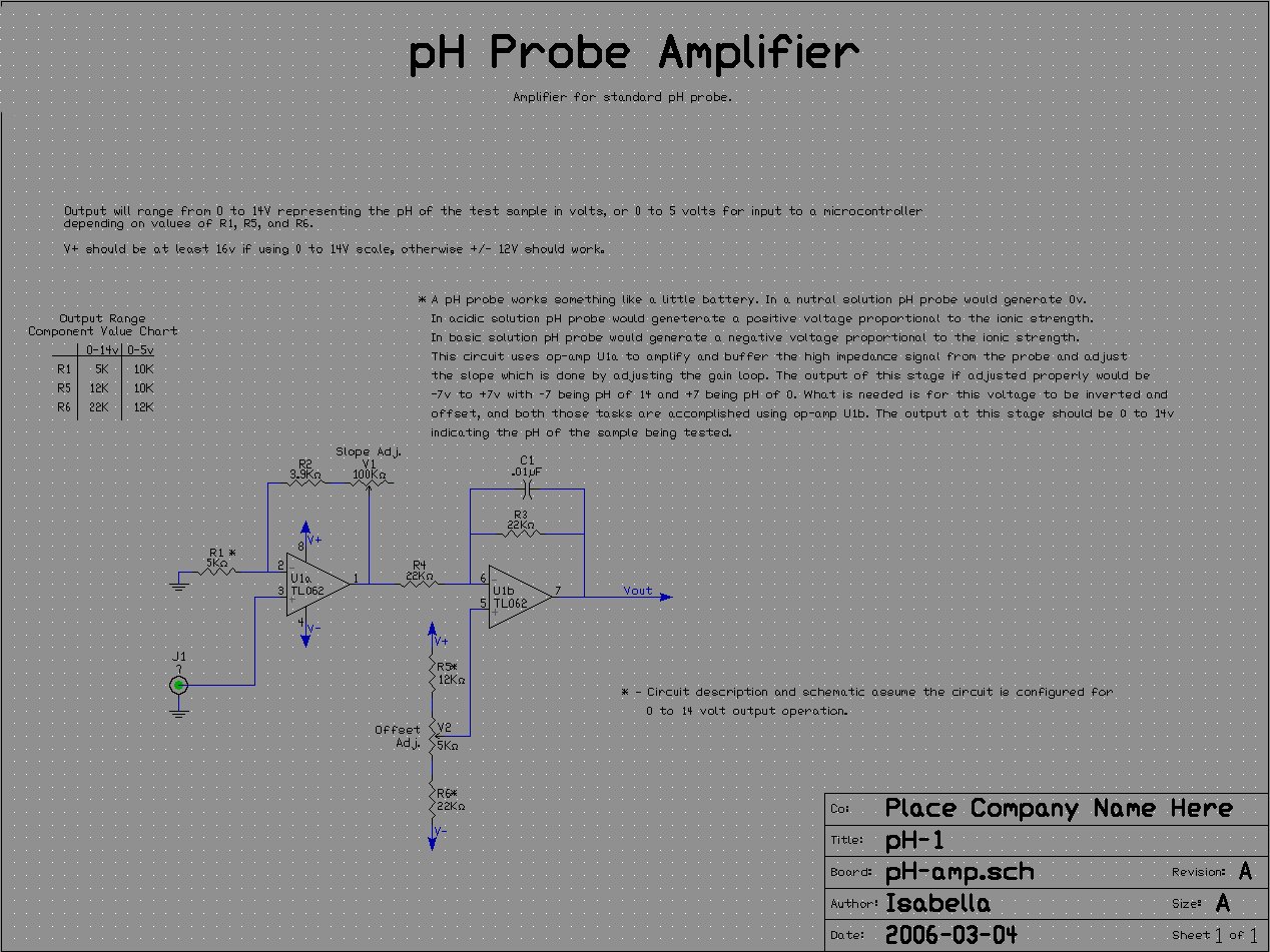
OK, So this is where I am up to. I have used this schematic
and the basic circuitry of the NerdKit including the LCD display to try and build my pH sensor. HOWEVER it has not worked!. When I connect the battery the LCD shows no life. I know its the additional circuitry that is causing the problem because when i remove it the LCD works. Below are some pictures to show what ive done. I Am using a TL062CP op-amp just like the one in the pH schematic. If i was to guess whats wrong i would say that my attempt at copying the schematic hasnt worked. i have used the same value resistors (for the voltage reading to be between 0-5V). The potentiometer could be an issue i dont know if thats wired up correctly. Also where ever it says on the schematic V+ i have wired it to the +5V rail and for V- have wired it into the ground rail. Also on the BNC jack, one wire is going into ground(green) and the other (black) is going into pin3. As i am new to electronics so i do not know what things i should be doing to debug the system. I hope I have given enough info for this post to be of any use. I Would like to Thank everyone in advanced for helping me. If you have any questions ill do my best to answer them. Kemil
|
|
December 24, 2010 by kemil |
Ive managed to get power. It was the potentiometer. I took the +5v lead out and switched it to the ground and then took the lead that was originally in the gnd rail out completely and i have a functioning lcd screen. Next step is to reprogram the microcontroller. Going to start by Just getting ADC values between 0 and 1024 and displaying them on the ldc then going to calibrate the probe. kemil |
Please log in to post a reply.
|
Did you know that any circuit of voltage sources and resistors can be simplified to a "Thevenin" equivalent circuit? Learn more...
|


Copyright © 2013 by NerdKits, L.L.C.


