NEW: Learning electronics? Ask your questions on the new Electronics Questions & Answers site hosted by CircuitLab.
Support Forum » (Weighscale Project) AD620 Instrumental Amplifier
|
December 09, 2010 by bdubb427 |
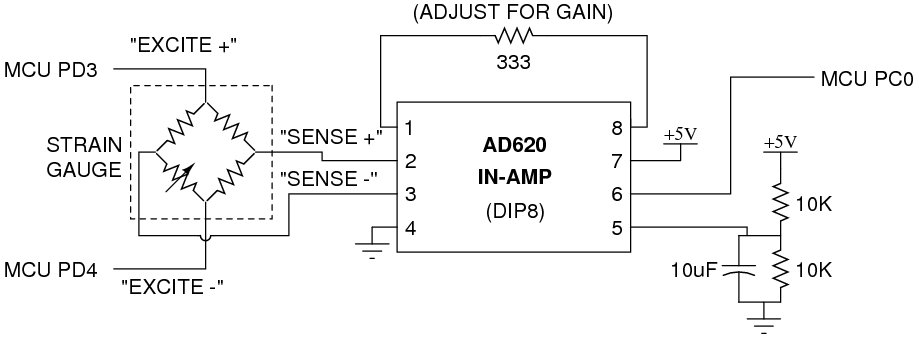
I'm having trouble working my AD620 in-amp. I found a schematic of the ad620 in a different thread, here it is:
I am attempting to just test the IN-AMP to see if it works. So instead of using the sense/excite wires like shown in the schematic, I am driving a direct voltage into the In+ and In- inputs, and just measuring the output with a multimeter Also, I am unsure of what pin 5 does with the 5volts in a voltage divider, so I ended up grounding that pin. Also, what I have noticed is that this schematic does not match the one I have googled online, here it is:
I set my circuit/pins up to match the 2nd image that I googled online. Why are these two setups different? Are they two different AD620 in-amps? Anyhow, after driving a very small voltage into -In and +In (I grounded -In, and drove 5mV into +In), I am unsure what to do with the -Vs pin... and I am assuming that +Vs pin is just the 5volts for power. So for now, I just grounded the -Vs pin. I am recording a gain, that end up being around 700mV. The problem is, this gain does not vary with my +In voltage of 5mV, or the Rg (gain Resistor). I don't know what the problem is, or If i am following the wrong schematic. |
|---|---|
|
December 09, 2010 by bretm 
|
I don't see any difference between your schematic and the connection diagram. You have positive and negative power supply to Vs+ and Vs- like you should. Your inputs are going to -IN and +IN like they should, your gain resistor is connected to the Rg pins like it should be, you have the reference voltage at REF, and you're measuring the output at OUTPUT. It's all good. What I was saying in the thread where you started is that the specs for this chip don't allow the inputs to go all the way down to Vs-. You were trying to put 0V and 50mV at the inputs, but the allowed range for the inputs is something like Vs- + 1.6V (minimum) to Vs+ - 1.6V (maximum). Since Vs- is 0V and Vs+ is 5V, that means your inputs have to be in the range 1.6V to 3.4V. The output is also restricted to approximately that range. (The inputs allow actually a slightly larger range than this but I'd keep to this range to avoid distortions.) So try putting 2V and 2.05V across the inputs and then measure the output, then increase the difference to 0.1V, and then 0.15V, etc., and see if the output varies. The output when both of the inputs are the same and within the valid range should equal REF. In this case that's 2.5V because of your voltage-divider. There may be some amount of load at the REF pin and this may be pulling down the voltage from the divider (which may be why the datasheet shows driving the REF pin with an op-amp voltage-follower after the voltage divider), so measure the voltage at the REF pin to see what the common-mode (zero difference between +IN and -IN) output should be. Then put the 50mV difference between +IN and -IN and see how much the output differs from REF. It should be 50mV times the gain, as long as the output would be within 1.6V and 3.4V. Outside that range it may clip. |
|
December 09, 2010 by bdubb427 |
Ok, I understand what you are trying to say now. I have inputed a 2.0v and 2.05v input (.05 V difference) and tried varying it to see if the output varies. It does vary, which I am happy to see. Unfortunately, even though I measure the reference voltage to be 2.5v, when the voltage difference in the inputs(+/-) is ZERO or close to zero, the output isn't 2.5 as expected. It's about 3.26 volts. I am unsure where this gain is coming from. |
|
December 09, 2010 by bdubb427 |
"something like Vs- + 1.6V (minimum) to Vs+ - 1.6V (maximum). Since Vs- is 0V and Vs+ is 5V, that means your inputs have to be in the range 1.6V to 3.4V. The output is also restricted to approximately that range." From what I understand, my inputs cannot be close to ground, so it has to be within that range. But my question is... isn't the voltage coming from the "sense" wires of the weighscale supposed to be an extremely small voltage? I'm assuming it's so small that it's close to 0v? How would I be able to measure this voltage if my range for input is approximately 1.6v to 3.4v? |
|
December 09, 2010 by bretm
|
I don't know why it would be 3.26V instead of REF when the inputs are both the same. The voltage difference from the sense wires may be close to zero, but they'll each about about 2.5V because they come from the middle of a bridge that is sort of like a voltage divider where the top and bottom resistances match. |
Please log in to post a reply.
|
Did you know that NerdKits has been featured on Slashdot, Hack A Day, Hacked Gadgets, the MAKE blog, and other DIY-oriented websites? Learn more...
|


Copyright © 2013 by NerdKits, L.L.C.