Halloween Project: The Human Theremin

As we have mentioned before, we always like to use Halloween as a chance to show off neat homemade electronics to the general public. In this special Halloween video tutorial, we have recreated the idea behind a musical instrument called the theremin, and built one into a Halloween costume. This not only gives you the ability to wear a costume that is loud and very likely obnoxious, but also to have a costume that is fun for others to interact with. The project uses two infrared distance sensors, as well as PWM (Pulse Width Modulation) and a piezoelectric buzzer to create a sound, and brings together quite a few concepts to make the whole thing work.
Click any photo to enlarge:
Background
This project recreates the properties of a musical instrument called the theremin. A theremin is played without the performer having physical contact with the instrument. A "normal" theremin uses two antennas and changing electric fields to sense the position of the players hands (not unlike our previous Capacitive Proximity Sensor from last Halloween); one hand controls the pitch of the note, and the other hand controls the volume or amplitude of the note.
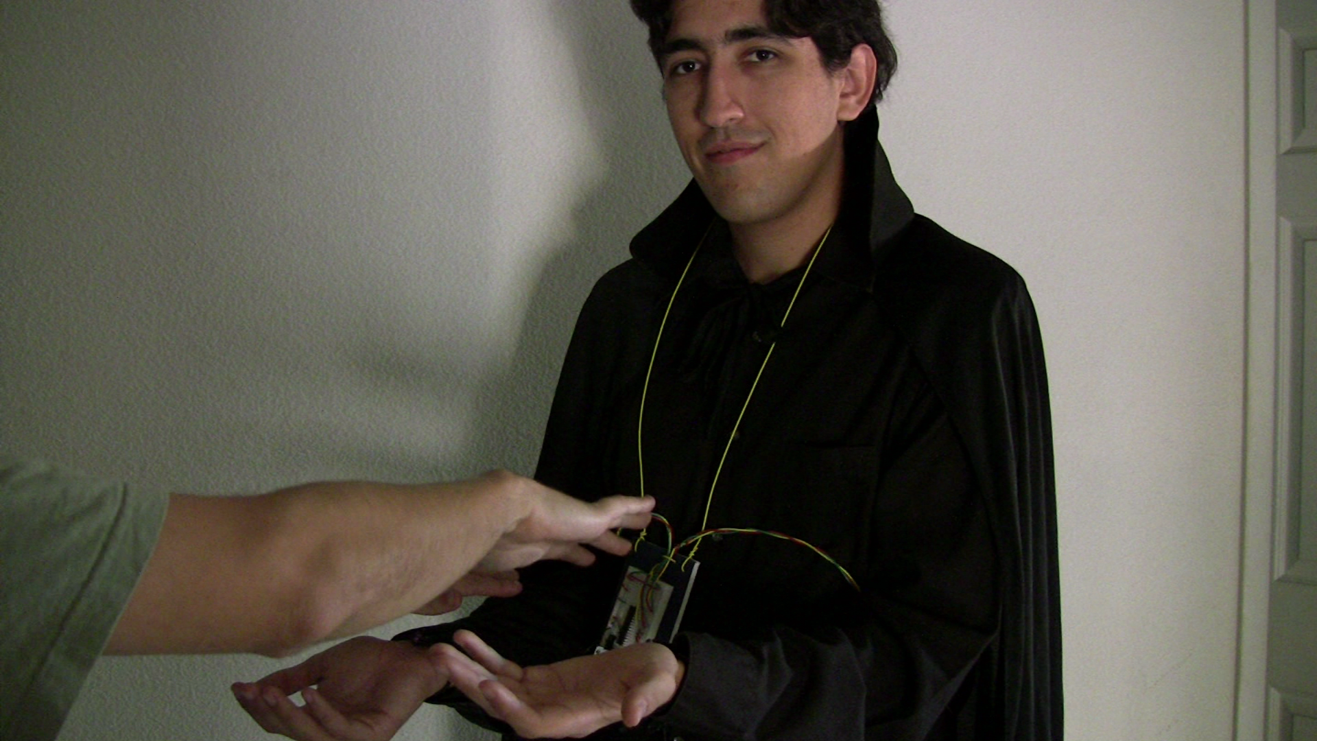
The idea behind this costume is to recreate the function of a theremin and build it into a Halloween costume, giving someone that approaches you while trick-or-treating the ability to wave their hands and make music with your costume like a theremin.
The Electronics
For our theremin, we need two distance sensors: one to control the volume of the note being played, and the other to change the pitch. We decided to build two simple IR reflectivity sensors which measure how much infrared light is reflected from a nearby target. When a target (like the player's hands) is brought closer to the IR LED and phototransistor pair, more light is reflected back into the sensor.
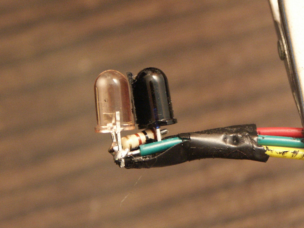
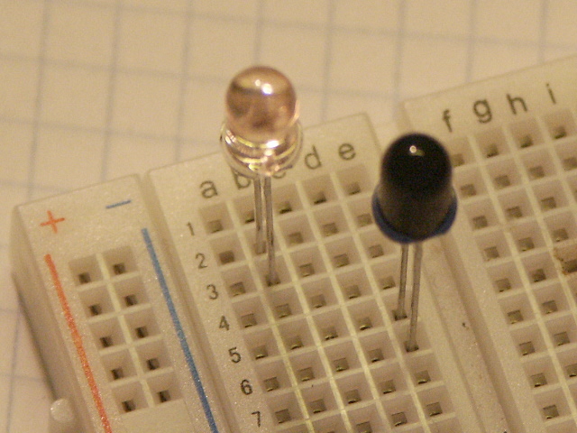
As shown in the photos above, the IR LED and phototransistor are placed in close proximity and are pointed parallel to each other. The circuit we are using for each sensor looks like this:
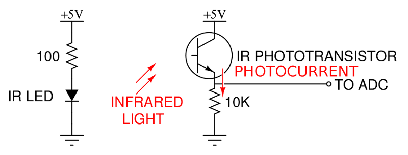
The IR LED is just like any other LED, in that a current-limiting resistor is useful to control the device current and therefore the light intensity. With a 100 ohm resistor and the approximately 1.5V forward voltage drop of the IR LED, we'll have a LED current of about 35mA. That's fairly high, but more light emitted will yield more light coming back to our sensor.
The phototransistor is a device with an exposed silicon junction. When light passes through the plastic casing, most non-IR wavelengths are simply absorbed by the plastic, but the infrared light makes it to the sensor within. Each photon striking the silicon junction causes an electron to flow. Because this is a phototransistor and not a photodiode, this current is multiplied by the transistor's current gain, so each photon may actually cause perhaps 10 to 100 electrons to flow. This current has nowhere to go except through the 10K resistor, and as the current passes through the resistor, the voltage across the resistor rises (V=IR). This change in voltage is read by our microcontroller's Analog to Digital Converter (ADC).
The two resistor values are both "knobs" that can be adjusted to get the desired level of voltage as a hand is moved near the sensor. Increasing the 10K value will increase the output voltage proportionally, which is fine as long as the voltage doesn't saturate (as it can't go above +5V). Additionally, the presence of any background IR light (such as from natural light sources) will be amplified by increasing the 10K resistor value. The 100 ohm resistance can be made smaller to allow more current to flow through the LED, but this causes the battery to discharge faster.
Parts List and Assembly
In addition to one USB NerdKit, the following extra parts are needed to complete this project:
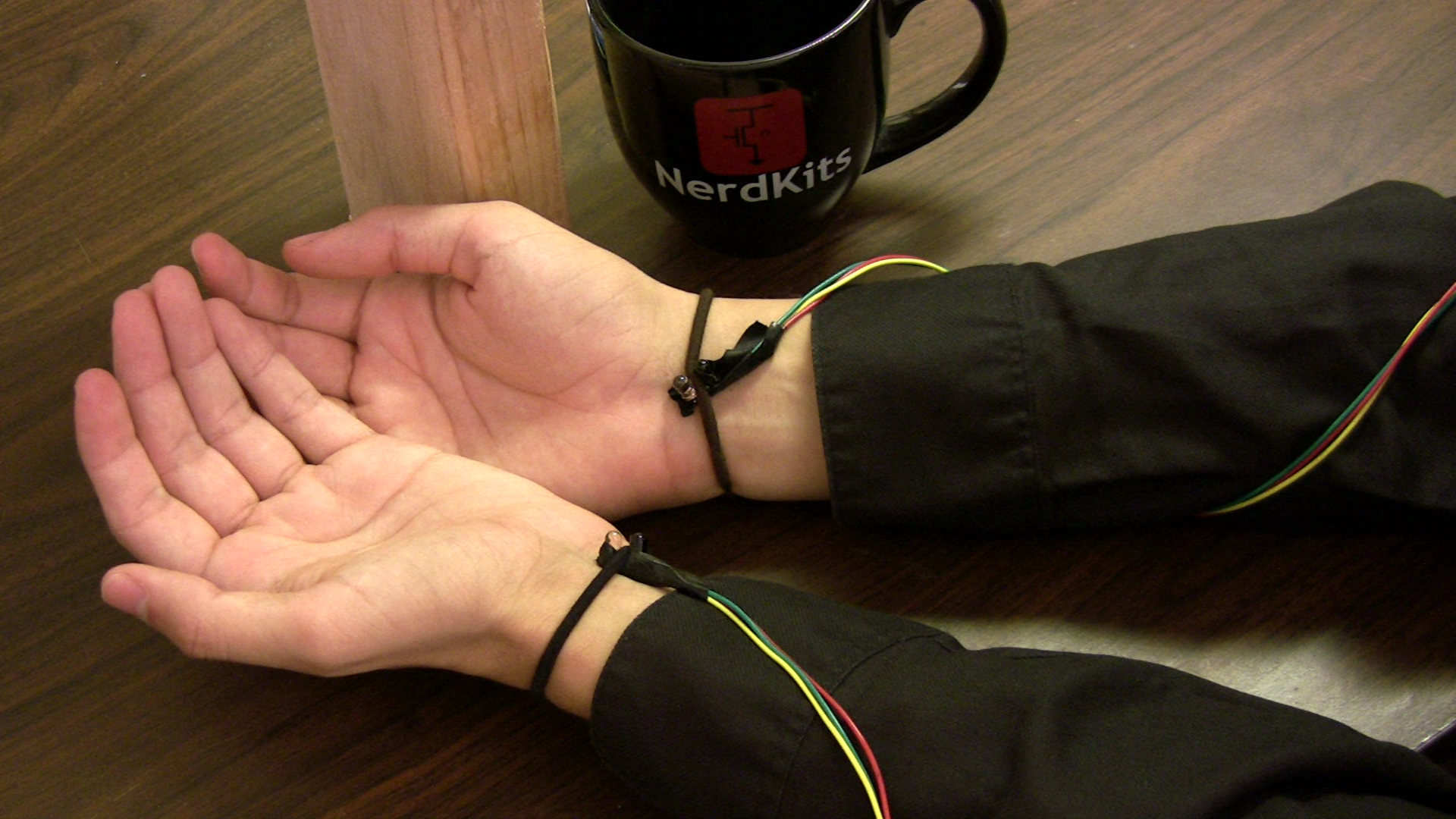
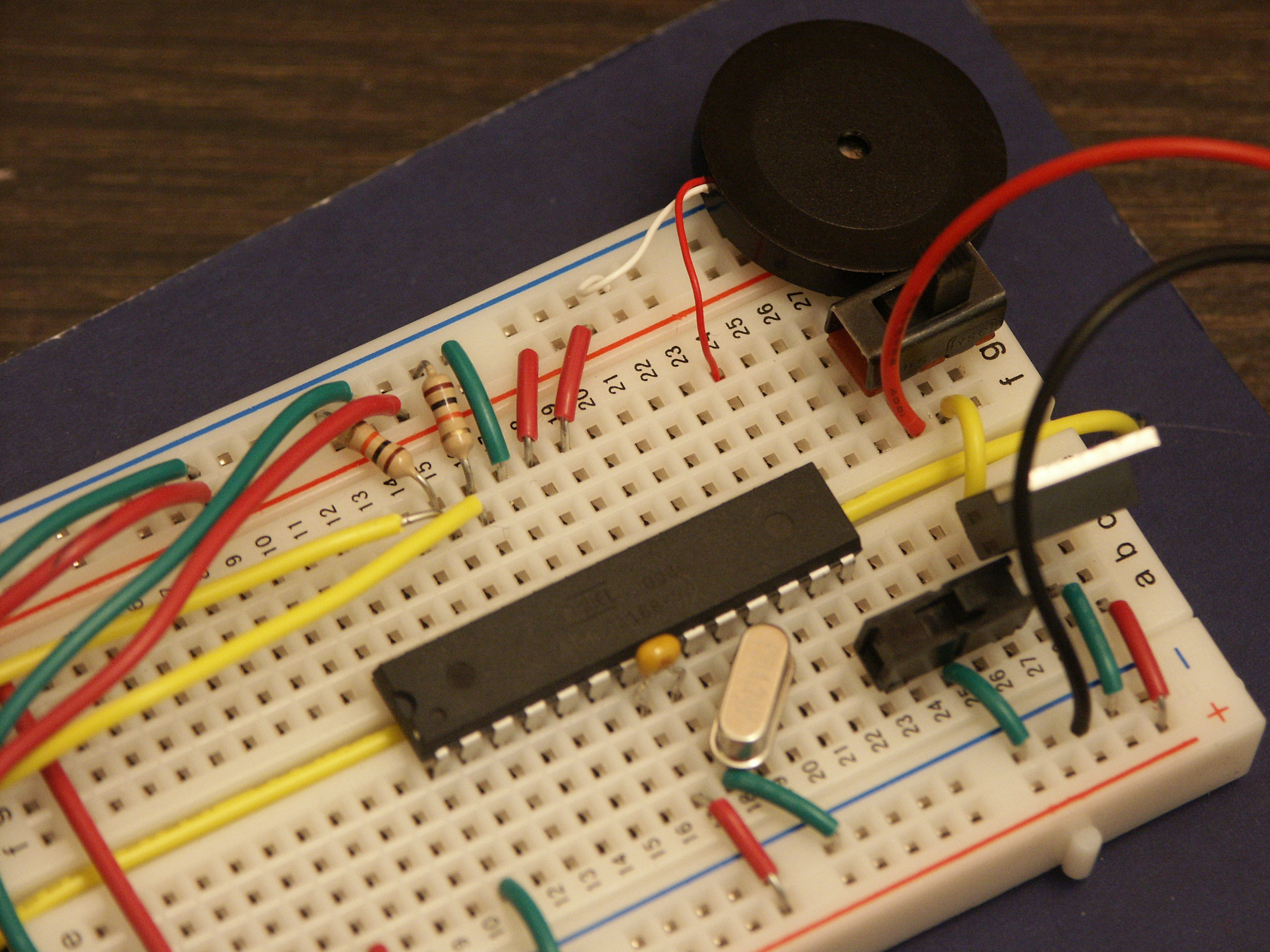
To assemble a sensor, complete the schematic shown above on your solderless breadboard. Test the sensor, and using a multimeter, read the voltage across the 10K resistor as you move your hand up and down. If you would like to make your sensor more permanent, you can solder it together as we have done, placing the IR LED, phototransistor, and 100 ohm resistor together on a 3-wire cable. The 10K resistor is then left to stay on the breadboard, which allows the receiver gain to be adjusted easily.
Please be aware that the physical orientation of the LED and phototransistor are very important. The IR LED has a narrow transmission angle, and the phototransistor has a narrow receiving angle. Make sure the two are pointed roughly parallel to each other, or perhaps tilted very slightly inwards. We've also used a small piece of electrical tape placed directly between the LED and phototransistor to prevent light from traveling directly from one to the other, because light that travels directly only contributes to saturating the phototransistor measurement, and isn't useful in sensing a target. You should experiment with the sensor as a simple analog circuit, and even try modifying the various resistor values to see how the behavior of the sensor changes.
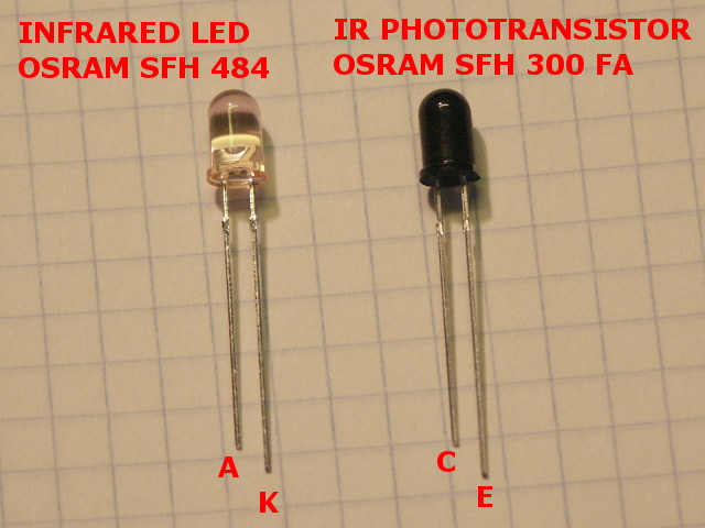
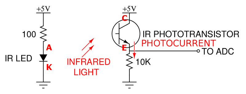
For the IR LED and phototransistor we are demonstrating, also notice that the orientation of the LED package in particular is reversed in comparison to normal T1-3/4 LEDs. For a "normal" LED, the anode is the longer lead, and the cathode has the shorter lead. However, the manufacturer of this part decided to build this LED in the opposite direction. The phototransistor is similarly reversed. If confused, consult the datasheets or the labeled images above.
This problem is especially troublesome since infrared light is invisible to the naked eye, and therefore we can't tell whether our LED is lit or not. There are two solutions here: first, using a multimeter, we can measure the voltage across the 100 ohm resistor to verify that roughly 35mA is flowing through the LED. (Current will not flow when the LED is reversed, so you would measure approximately zero voltage drop across the 100 ohm resistor in that case.) The other approach is to use a camera, such as a webcam or cell phone camera, to take a look at the infrared LED. While infrared light is invisible to the human eye, it will show up easily on most camera equipment.
The Code
Reading the sensor value is as easy as reading the value from the ADC. This is covered extensively in other tutorials, as well as in the NerdKits Guide where the temperature sensor is the first project. As usual when reading ADC values, we average over many samples to minimize jitter from noise as well as from the hands. One thing that is different about this project is we are reading from two different sensors instead of just one. To read from different sensors we use the ADMUX register to select which channel we want to read from. The ATmega168 chip we are using has 6 ADC channels you can switch between. The function adc_read(...) takes care of setting the ADMUX value and reading the ADC value.
In order to get a smooth and creepy sound coming out of the piezoelectric buzzer, we did have to do a few interesting things in the code. We go over how to create musical notes with the buzzer using PWM and square waves in our Making Music with a Microcontroller video, but in order to get a smoother sound we did a few things differently. The biggest difference is we output triangle waves at different frequencies instead of square waves. The code uses a timer running at full speed and an 8 bit PWM output like we have done before.
void pwm_timer_init(){
  //// begin math ////
  // clk = 14745600Hz (ticks per second)
  // with TOP value at = 0xFF
  // 14745600 / 256 = 57600Hz
  //// end math ////

  //using TIMER1 16-bit

  //set OC1A for clear on compare match, fast PWM mode, TOP value in ICR1, no prescaler
  //compare match is done against value in OCR1A
  TCCR1A |= (1<<COM1A1) | (1<<WGM11);
  TCCR1B |= (1<<WGM13) | (1<<WGM12) | (1<<CS10);
  OCR1A = 0;
  ICR1 = 0xFF;

  //enable interrupt on overflow. to set the next value
  TIMSK1 |= (1<<TOIE1);

  // set PB1 as PWM output
  DDRB |= (1<<PB1);
}
Notice we turn on the timer overflow interrupt for the timer. In the interrupt handler, we increase the PWM duty cycle for the next go around. Once the duty cycle reaches 255, it starts going back down again. Looking at the smoothed out version of this signal over time you can see how it creates a triangle wave. The output of the PWM is fed directly to the piezoelectric buzzer.
In this setup, the step size is what dictates the frequency of the note. If we increase the duty cycle by two instead of one we will climb to 255 twice as fast, therefore doubling the frequency. In the main loop, we alter the value of the step size proportionally to the number the position sensor is reporting for the hands.
There is one extra trick we had to employ in order to get the smooth pitch change. Notice above that I mentioned increasing the step size from 1 to 2 would double the frequency, which is quite a noticeable jump in frequency. In order to get a smooth pitch change, we want to be able to vary the step size by fractional amounts. To achieve this, we use something called fixed point math. Basically, we just used a 16-bit integer to represent our step size, but only use the most significant 8 bits when it comes time to increase the PWM duty cycle. This allows us to treat the bottom 8 bits of the step size a fraction of the step size. It can make the code a bit confusing to read to the untrained eye.
We employ a similar strategy to vary the volume of the current note. The volume of a note is the same as the amplitude of the note, so to decrease the volume of a wave all you have to do is scale down all its values by a constant factor. To adjust the volume in our system, we turn the value from the hand position sensor into a volume value between 0 to 255. The PWM output we would have set from the triangle wave generation code gets cast into a 16-bit integer and multiplied by the volume number. A volume level of full will result in a (nearly) unscaled PWM value, and any number less than 255 will scale the PWM values down.
Here is a snippet of code from the interrupt handler that does the PWM step increase, and the volume control. Notice how we only use the top 8 bits of the step variable, and take a close look at how we scale the PWM to achieve a volume effect.
uint8_t next_val(){
  // compute next phase, doing rollovers properly
  // [... omitted here -- see source code file ...]

  // compute next volume-weighted sample
  uint8_t raw = (uint8_t)(state>>8); // unweighted
  uint16_t rawweighted = raw * vol;

  return (uint8_t)(rawweighted>>8);
}
These left-shift-by-8-bit operations are just our way of telling the C compiler to look at the top 8 bits of each computed value.
Source Code
A lot can be learned from going over the source code, so go ahead and download it and give it a read.
More Videos and Projects!
Take a look at more videos and microcontroller projects!
Comments
|
Did you know that negative numbers are represented in two's complement notation in binary? Learn more...
|


Copyright © 2013 by NerdKits, L.L.C.