DIY Sous Vide Cooker with Feedback Control

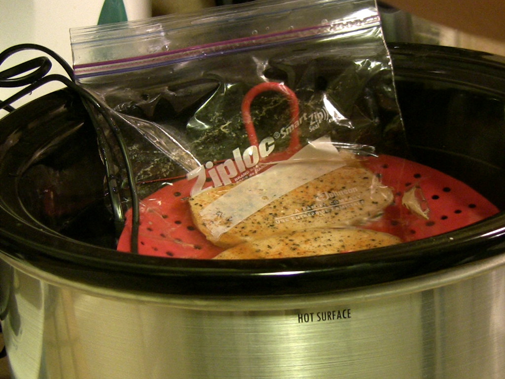
Sous-vide cooking involves cooking food in sealed plastic bags inside a temperature controlled water bath. It's a technique that's been around for a few decades, but is just beginning to be popular in the home kitchen. We decided to give it a try by using a NerdKits microcontroller kit plus some items from our local Wal-mart and Home Depot to construct a sous vide cooker. The result is tasty food with textures and consistencies that are simply unachieveable by conventional cooking techniques!
Normal cooking techniques, like heating in a pan or oven, rely on heating the outside surface of food via convection or conduction. That heat must then travel to the center of the food via conduction. That's why the center of a steak is always the most rare point -- it's last to heat up, and/or doesn't heat up as much. We apply very high temperatures to the surface, and we're done cooking when the center of the food has reached the desired (or safe) doneness. If you order a normal steak medium rare, it's medium rare in the center, with much more doneness toward the edges.
In contrast, sous vide cooks the food for a long time at the final desired temperature. A long time is required because heat has to conduct all the way through the thickness of the food, but the result is that a medium rare sous vide steak will be medium rare the entire way through the thickness. (After the sous vide, a quick high temperature sear provides a nice crust, but really only affects the outer millimeter or two.)
Click any photo to enlarge:
Warning: There are food safety issues associated with low-temperature cooking. Make sure you do it safely. We'd like to refer your to Douglas Baldwin's Sous Vide for the Home Cook which has excellent discussion of food safety, including tables of fish/poultry/meat pasteurization times at various temperatures.
Warning: Some parts of this project involve working with AC line voltage. If you're not 100% sure you can do it safely, don't.
Recipe: Succulent Sous Vide Scallops
Here's a video recipe we made for some incredibly delicious sous vide scallops:
Melt butter. Add salt, pepper, thyme. Coat scallops individually and add to bag. Vacuum seal bag. Cook sous vide at 122°F for at least 1 hour.
Controlling the Cooker
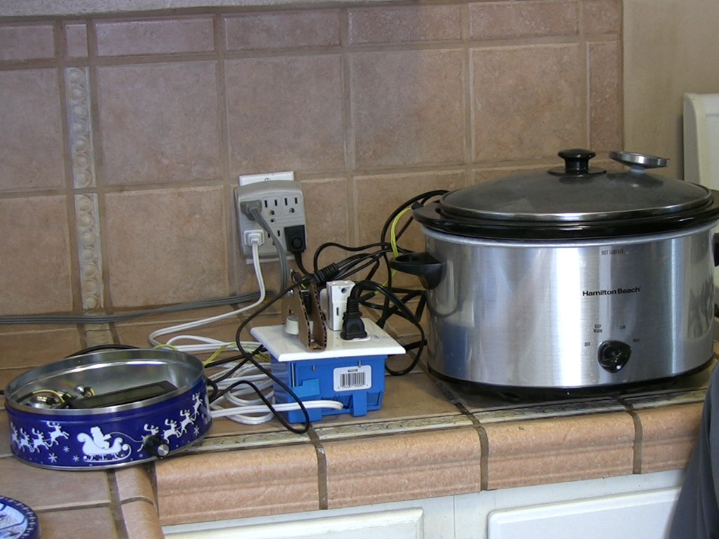
We used a rotary dimmer switch and receptacle in an enclosure for controlling the power delivered to the cooker. We actuate the dimmer's knob with an RC servo, which we discuss more in depth in our Servo Squirter video.
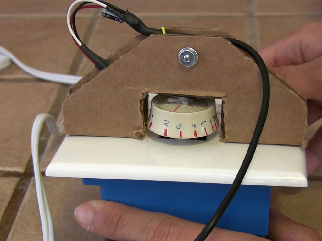
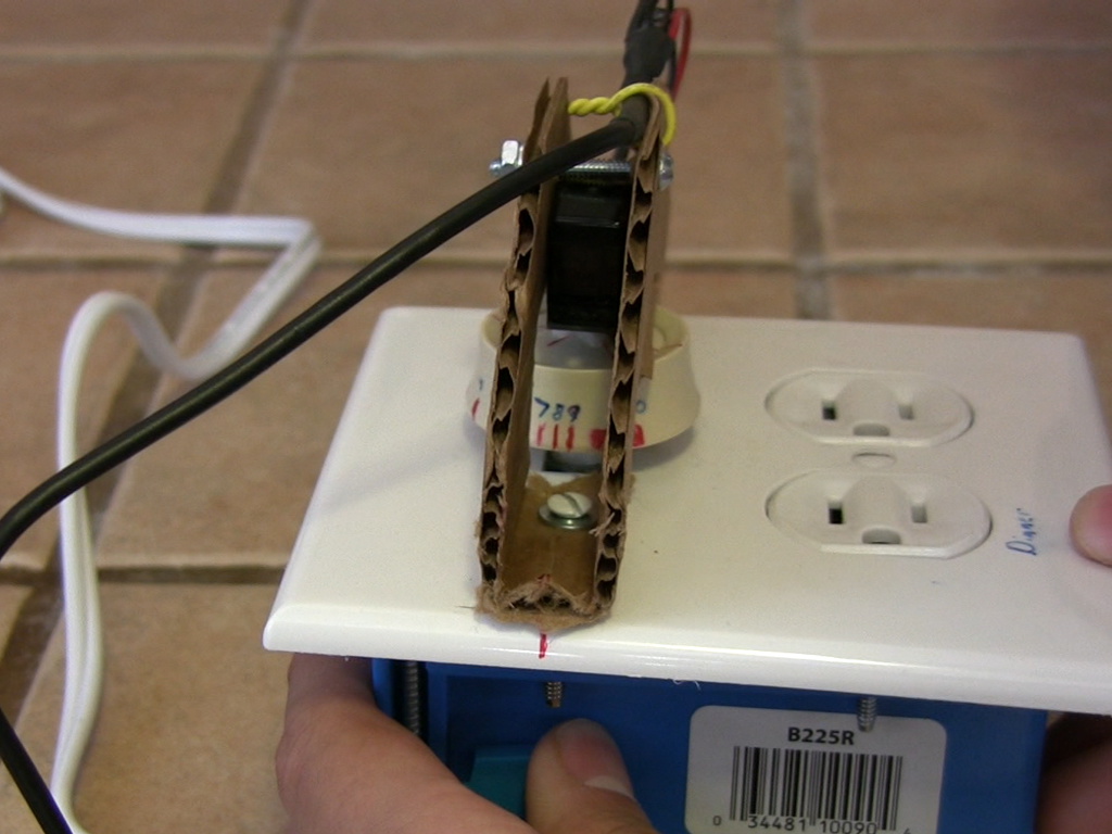
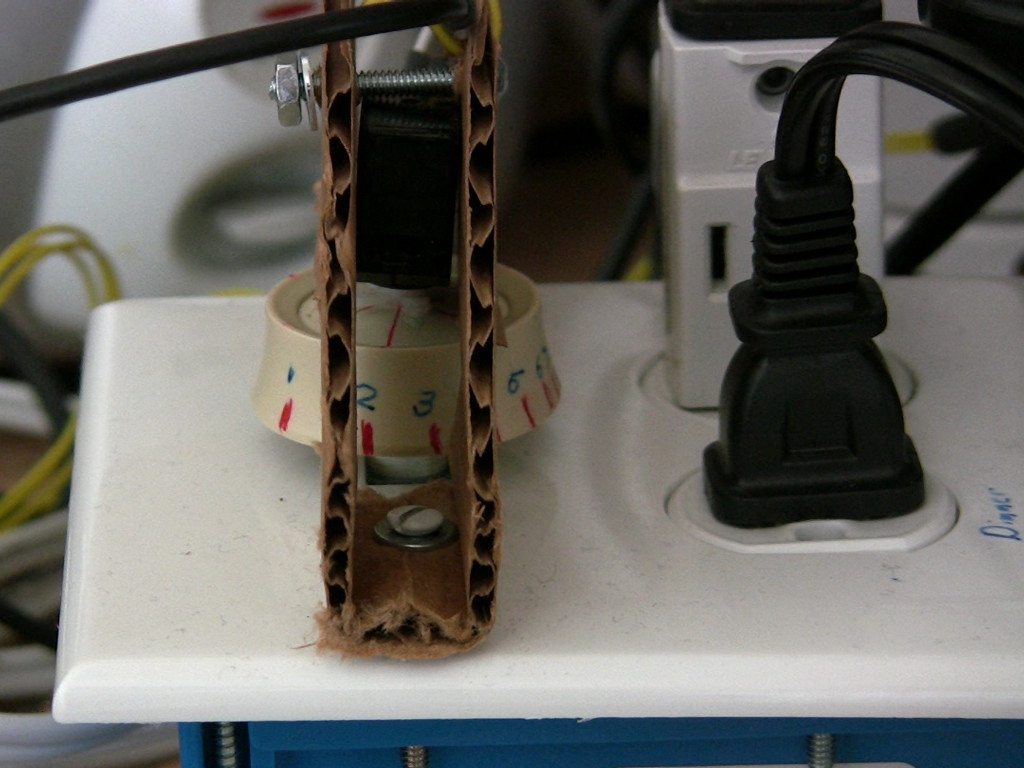
The dimmer switch's power delivery is not linear over its rotation range. Lower power settings are given disproportionately more angular range than the higher power settings. (This might be done because the human eye's response to light is logarithmic, or at least sub-linear, allowing us to perceive a wide dynamic range of light levels.) We ran the dimmer switch with a load and measured the resulting voltage with a multimeter, and from this were able to place markers on the knob that corresponded to 10%, 20%, ... 90%, 100% power levels. In software, we then constructed an approximate mapping from power level to angle, so our code's dimmer_set_power function tries to map power level to servo coordinates.
Analog to Digital Converter Tricks
We use the ADC in two different ways in this project:
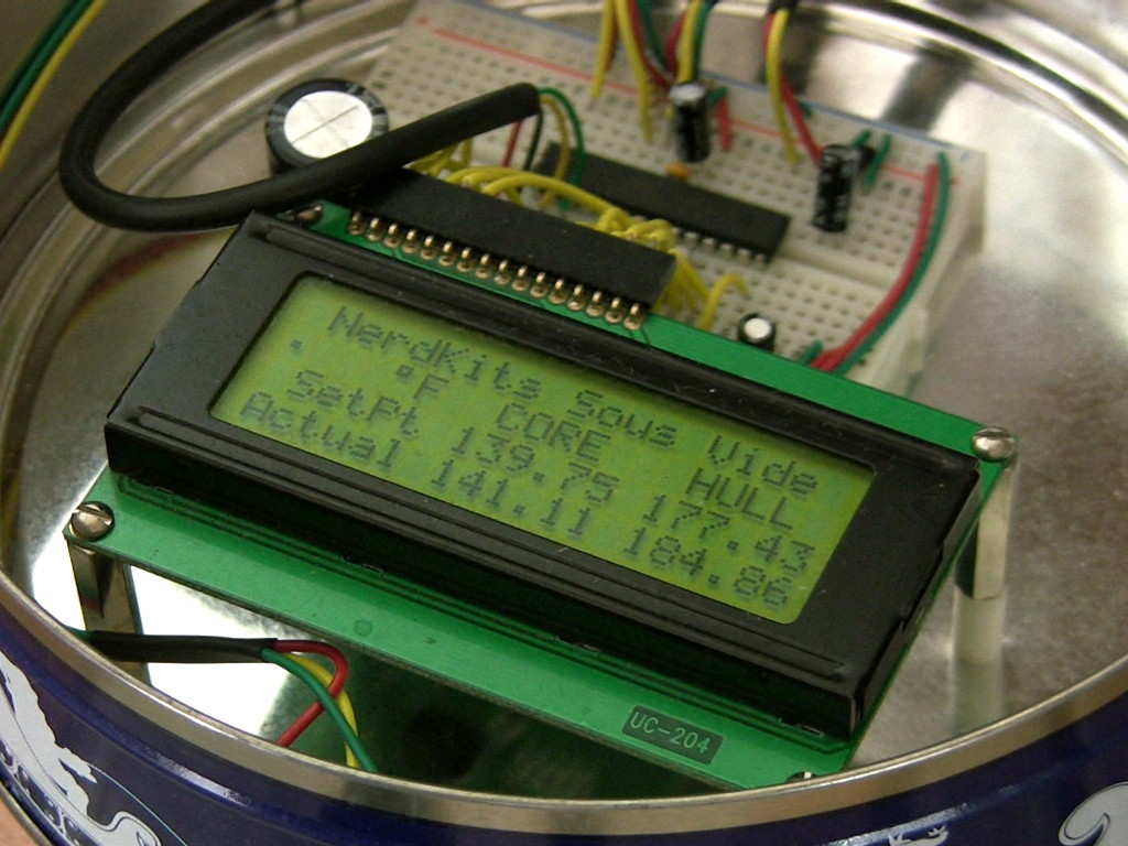
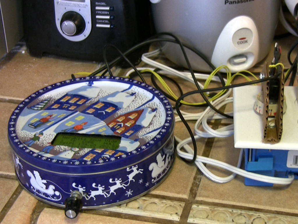
First, we use the ADC to read the desired temperature as set by a potentiometer. For this, we simply average over 100 readings, providing more than 10 bits of effective resolution. We then scale this to the 80°F to 220°F range -- both extremes near the limits actual ability of our system. This potentiometer, in combination with the LCD readout, lets the user accurately set a desired temperature.
Second, we use the ADC to read from our two temperature sensors. As the LM34 temperature sensors have an absolute output signal of 10mV/°F, the absolute value of the analog voltage is important -- not just its relative place on the scale of GND to VCC. To compensate for any possible variation in supply voltage, we use the microcontroller's built-in bandgap voltage reference, which provides a constant voltage reference at about 1.10 volts. (The exact value varies slightly from chip to chip, but can be calibrated and will hold well for that particular chip.) We use that to infer what the "true" VCC value is -- whether it's 4.500 or 5.500 volts. This lets us scale the ADC readings from the temperature sensors appropriately, and get a sense of absolute temperature regardless of the current supply voltage.
Operating the servo does cause a large amount of current to flow from the power supply briefly, which does cause a great deal of noise in all of the analog readings. Because of this, we only update the servo occasionally (once every 10 cycles through the main loop), and therefore the readings used to calculate the new servo position are always "clean" readings.
Thermal Modeling
Thermal systems like our crock pot can be modeled mathematically by using linear (or non-linear) electrical equivalent circuits. This lets us use circuit simulation tools like CircuitLab to find temperatures and heat flows. We can make these thermal models by creating a conceptual (and numeric) self-consistent mapping between electrical systems and thermal ones:
| Electrical Concept / Quantity | Thermal Concept / Quantity |
|---|---|
| Voltage [V] | Temperature above Ambient [K] |
| Charge [C] | Heat Energy [J] |
| Current [A] | Heat Flow Power [W] |
| Capacitance [F] | Thermal Capacitance [J/K] |
| Resistance [Ohm] | Thermal Resistance [K/W] |
| Constant Voltage Source [V] | Constant Temperature Surface [K] |
| Constant Current Source [A] | Constant Heat Flow [W] |
As charge is conserved as it flows around electrical circuit network (Kirchoff's Current Law), so is heat energy conserved in a thermal circuit network (First Law of Thermodynamics). Just as a voltage difference will cause charge to flow through a resistor (Ohm's Law), a temperature difference will cause heat energy to flow through a thermal resistor (conduction, convection, radiation). If you're curious to go deeper into this modeling concept, some recommended reading is Mathematical Models of Thermal Systems, as well as Lumped capacitance model.
Let's try to add some numbers for our specific sous vide problem. If we have about four liters of water in our crock pot, that's a mass of about 4 kg, and with a specific heat capacity of approximately 4184 J/kg/K, that's a thermal capacitance of about 4*4200 = 16800 J/K. (That 16.8 number is something we can use in our circuit simulation software as though it were a capacitance in Farads.) The ceramic crock pot itself weighs about 3 kg, and if we use an approximate specific heat of 800 J/kg/K, that's a thermal capacitance of about 3*800 = 2400 J/K.
Thermal resistances may be a bit tricker to understand, but ultimately, heat travels between two points via conduction, convection, or radiation. Each of these mechanisms has a heat flow rate that's dependent on the temperature difference between the two points. Conduction is generally quite linear (heat flow proportional to temperature difference), while convection and radiation are not. Let's first look at conduction through the walls of the ceramic crock pot: it's about 2 cm thick, and there's about 400 cm^2 (or 0.04 m^2) of surface area on each side. We don't know exactly what the ceramic material is, but we can guess a thermal conductivity of about 5 W/m/K. That gives us a thermal resistance of 0.02/0.04/5 = 0.1 K/W. Now, this is a big approximation since we're going to be looking at a larger system, but we can calcuate the "time constant" imposed simply by the ceramic crock pot's thermal resistance and capacitance:
τ = R*C = (0.1 K/W)*(2400 J/K) = 240 seconds = 4 minutes
or if we include the capacitance of both the crock pot and the water:
τ = R*C = (0.1 K/W)*(2400+16800 J/K) = 1920 seconds = 32 minutes
Those are long time constants -- far longer than we're used to seeing with electronic R and Cs, but real nonetheless. Thermal systems can be quite slow!
We have to estimate a few more parameters to get a reasonable thermal model:
Now we can put together a thermal equivalent circuit model, as shown below: (click to open the model in CircuitLab)
You'll notice that we've spit the crock pot thermal resistance in half, with the capacitance in the middle. In truth, we're really looking at a distributed system, where the capacitance and resistance are intermixed in the same space. However, we have to use lumped element approxmations to simplify the problem and get it into a language we can work with, and one way we do that is by splitting up the Rs and Cs to get the model close enough. We could add more R and C sections to model the crockpot, for example 3 Rs and 2 Cs, or 11 Rs and 10 Cs, and would get slightly more accurate results.
If we run the slow cooker's 250 Watt heater at full power for ten minutes, here's the temperature response, as predicted by our thermal model: (click to enlarge)
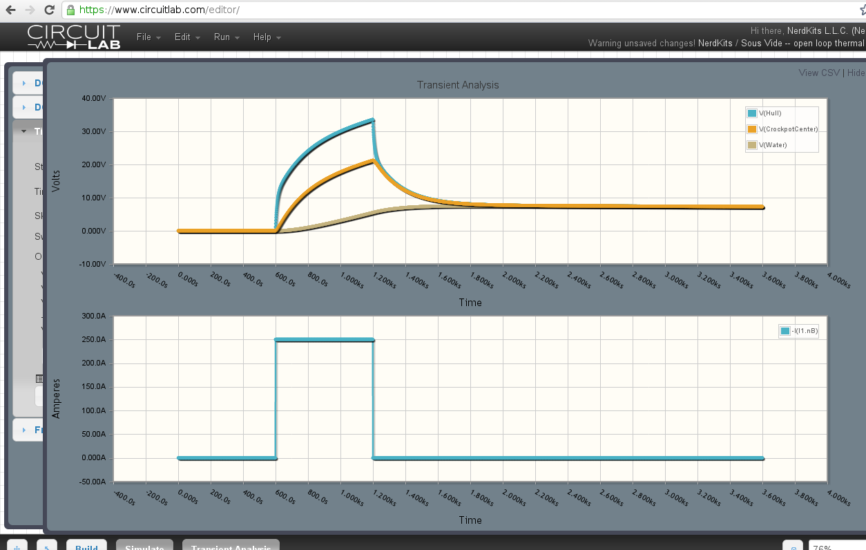
Even though the heater is only on for 10 minutes in this demo, due to the energy that gets stored in the crockpot, the water temperature doesn't hit its maximum until about 12 minutes after the heater has been shut off!
You can edit the thermal model and re-run the simulation for yourself. Just open the circuit, click "Open in editor", and then press F5 to run the simulation!
Inner and Outer Feedback Loops
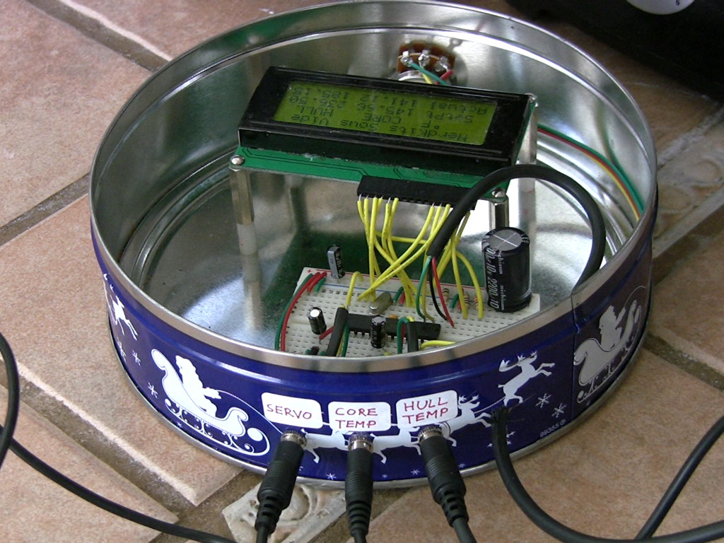
In the video we discuss our two-sensor control strategy and how and why we came to use it for our sous vide controller. We have an inner feedback loop which manages the hull temperature, which is the temperature in the space between the heater and the outer wall of the ceramic pot: (click to open the block diagram)
The inner feedback loop consists of block elements G1 and H1. G1 represents the servo and dimmer switch, as well as the thermal system between heater and hull. H1 represents the controller we've implemented in software. It's a simple proportional controller, and if x = Target_Hull_Temp - Hull_Temp in °F, then f(x)=0.30+0.05*x, where f(x) is the commanded dimmer power between 0 and 1 (100%).
Around this inner feedback loop we've built an outer feedback loop which manages the water temperature, and adjusts the desired temperature gradient across the ceramic pot: (click to open the block diagram)
G2 represents the thermal system between hull and water. H2 represents another proportional controller we've implemented in software. Again, it's a simple proportional controller, and if x = Target_Water_Temp - Water_Temp in °F, then f(x)=50+10*x, where f(x) is the commanded temperature difference across the ceramic pot. (Since heat conduction occurs at a rate proportional to the temperature gradient, this lets us control the rate of heat flow into the water quite directly.) The microcontroller takes this calculated f(x) and adds the current water temperature to it to get the commanded hull temperature, which becomes Target_Hull_Temp in the inner loop as described above.
As discussed in the video, the dual sensor inner/outer feedback loop strategy provides unique advantages over a single sensor design, and keeps our design and code simple.
Using CircuitLab we can combine the thermal model and control loops and simulate the entire system. Try opening this schematic and running the simulation:
The resulting simulation looks like this: (click to enlarge)
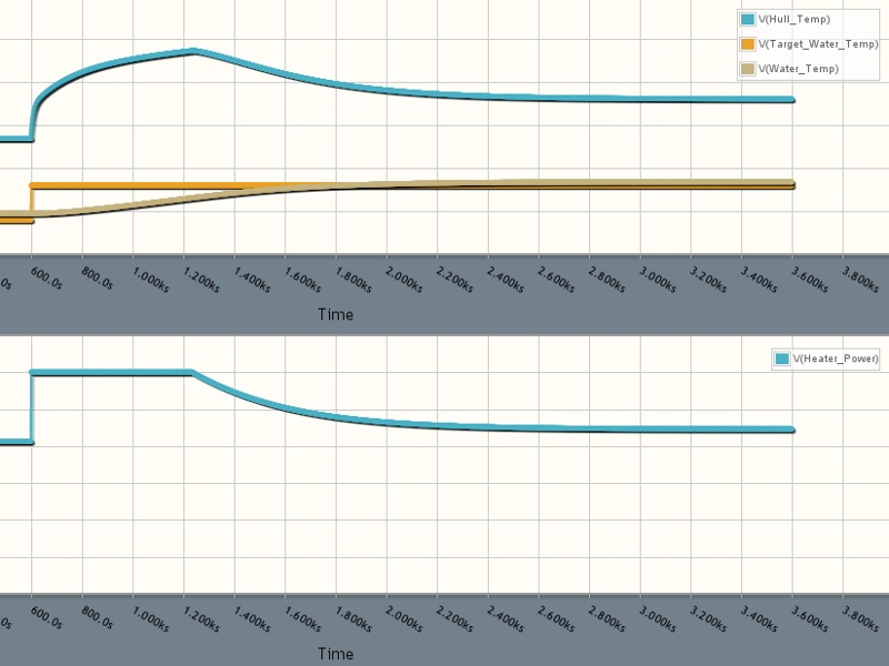
You can tweak the thermal model or controller gains and re-run the simulation see that it's quite a robust controller. You can also modify the H2 controller and try to add an integral term to eliminate the steady-state error! But even as-is with two simple proportional loops, it responds quickly and holds temperature.
Parts List
In addition to one USB NerdKit, the following extra parts are needed to complete this project:
Source Code
You can download the microcontroller source code here.
Schematic
More Videos and Projects!
Take a look at more videos and microcontroller projects!
Comments
|
Did you know that you can connect a computer keyboard to your microcontroller? Learn more...
|


Copyright © 2013 by NerdKits, L.L.C.