Robotic Xylophone

With the holiday season approaching, we are always looking for a way to add a little Christmas spirit to our office. This year, we thought it would be awesome to have a musical instrument that we could control with a NerdKits microcontroller kit, and have it play holiday music. Keeping true with the NerdKits spirit, we decided to build a xylophone, build the whole thing from scratch, and teach about solenoids and shift registers along the way!
Xylophone Construction
Our homemade xylophone was a great way to put our milling machine to use cutting the bars for each note, and using the lathe for the solenoid forms and steel slugs. We made our xylophone from aluminum bars -- all 6061 aluminum alloy rectangular bars, with a 1.5" x 0.375" cross-section. We made the base from a 1/8" thick sheet of acrylic (a transparent plastic). Each bar is supported at two points, with 3" long #6-32 machine screws passing up from below the acrylic base.
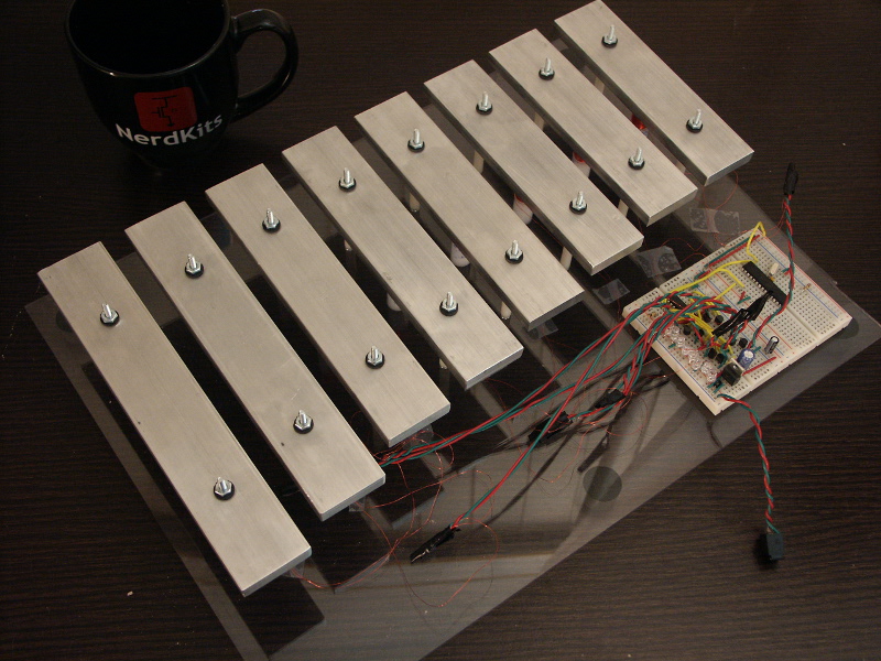
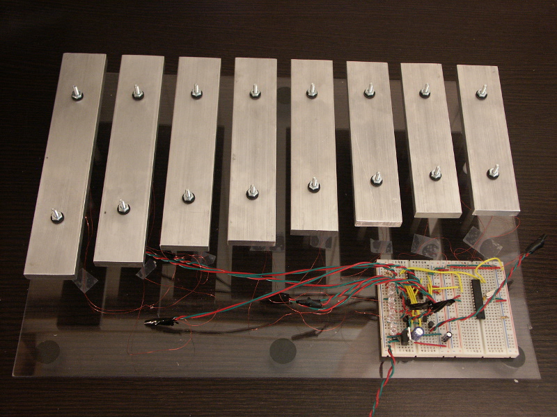
We used a 1.5" long nylon spacer, plus three #6-32 nuts, plus one rubber washer to set the height of the bar above the acrylic. On top of the bars, there is another rubber washer, and finally a nut lightly tightened. As expected, we found that the tightness with which the bar is held dramatically affects the sound of the instrument.
As described in the video above, we were able to adjust the length of the bars to get the note frequencies we wanted. We made use of the book "The Theory of Sound, Volume 1" (full text via Google Books) by Lord Rayleigh, and specifically the chapter titled "Lateral Vibrations of Bars", as a reference. As described in the video, this explained that "for a given material ... the frequency of vibration varies ... inversely as the square of the length" (pp 219-220). That fact let us measure the frequency and length of one bar, and then set up a spreadsheet to calculate all of the lengths that we needed to get a single octave (C-C) of the C major scale (8 notes total -- no sharps/flats). Here's an excerpt of our spreadsheet for the 8 xylophone bars we ended up manufacturing:
| Note | Frequency (Hz) | Bar Length (mm) | Node Position (mm) |
|---|---|---|---|
| C6 | 1046.5 | 216.1 | 48.4 |
| D6 | 1174.7 | 203.9 | 45.7 |
| E6 | 1318.5 | 192.5 | 43.2 |
| F6 | 1396.9 | 187.0 | 41.9 |
| G6 | 1568.0 | 176.5 | 39.6 |
| A6 | 1760.0 | 166.6 | 37.4 |
| B6 | 1975.5 | 157.3 | 35.3 |
| C7 | 2093.0 | 152.8 | 34.3 |
In practice, when we started to make our bars, we made each a few millimeters longer than the equations suggested. Then we measured the frequency again, and made a final milling pass to the final length. You can download the full spreadsheet PDF, but if you're going to build this, you should try measuring the frequency of a few test cut lengths on your own! (The numbers shown in the table above and in our spreadsheet PDF are not necessarily the final lengths -- they were used only as a guide, with initial cuts made a few millimeters longer than the "Bar Length" shown, and final tuning done on each individual bar based on the equations but without the aid of the spreadsheet.)
The "Node Position" column in the above table is a position that's about 22.4% of the way from either end of the bar. As we talk about in the video, that's where we drill a hole to mount the bars. That location is special because it's a node of the vibration mode that we're looking for. Since it's a node, there's the least movement there (theoretically zero), so there is less opportunity for energy to be lost to the supports.
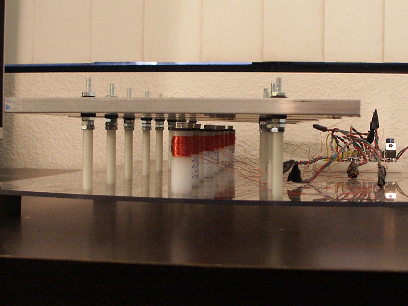
Our Solenoids
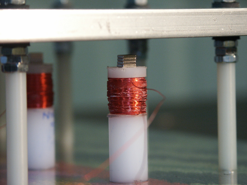
Using the lathe, we made our own solenoid forms, wound our own coils, and made our own solenoid steel slugs as well.
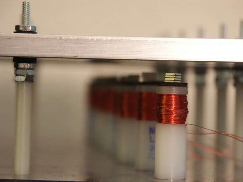
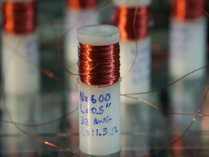
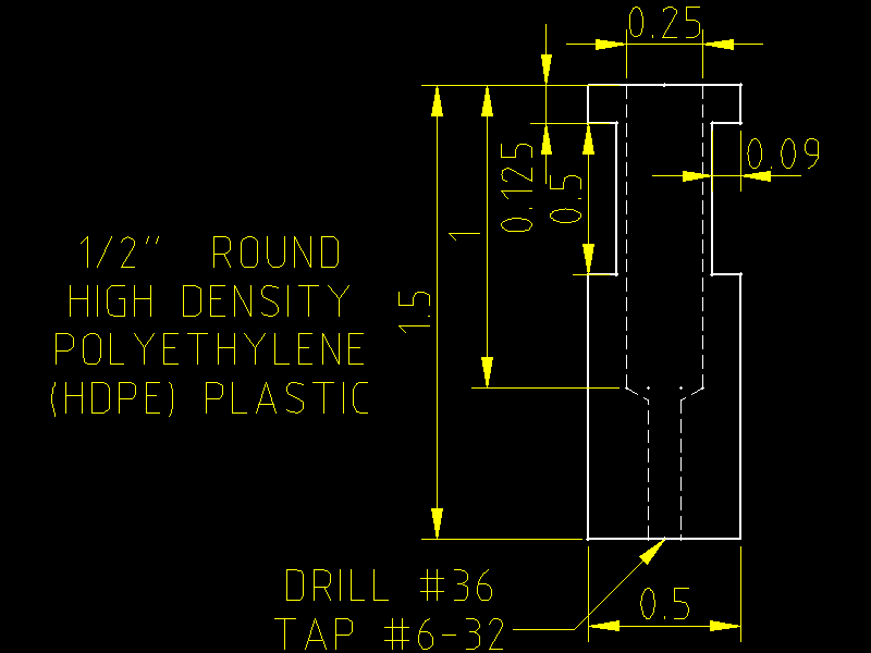
Our solenoid forms were cut from 0.5" diameter HDPE (plastic) round stock, and featured an outer channel 0.090" radially deep, leaving just 0.035" radial wall thickness to support the coil. The inner bore of 0.250" allowed the slug to slide up and down, and the slug returned to its base positions simply via gravity. Each coil received 600 turns of 32 AWG magnet wire, for a final measured resistance of approximately 11.5 ohms per coil. Magnet wire is just normal copper wire with a very thin enamel insulation layer, visible here with a red coloration. By having an extra-thin insulator, we can pack more turns into the same space. Finally, the bottom of the solenoid form is tapped #6-32 so that they can easily be screwed into place.
 /
/
As we mentioned in the video, we modified the solenoid concept slightly by adding permanent magnets to the mix. This lets us create a repulsive force that actually pushes our magnets and steel slug vertically up toward the xylophone bars. The role of the steel slug is two-fold: first, it is a mechanical guide to keep the travel of the solenoid's strike element vertical. That's why we made our slugs with a 0.230" outer diameter, which worked well for them to slide in the solenoid form's 0.250" round channel. Second, the steel slug serves a magnetic role, providing a "low-reluctance" magnetic field path, and letting the field lines exit more consistently radially along its length. However, if we made the slug too heavy, the gravitational potential energy requried to lift the slug would become quite significant, so after much testing, we partially hollowed out the slugs with a drill bit. This lets us guide the solenoid and the magnetic field, but still be light enough to have good lifting action. By making the steel slug lighter, we're able to put more of the solenoid's energy of each firing into kinetic energy.
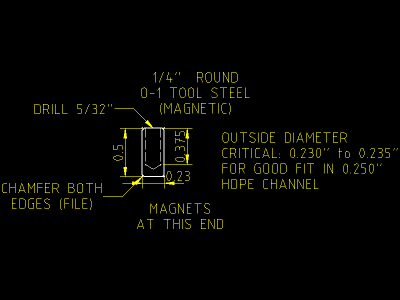
We added four magnets to the top of each slug. Each was a high-strength N50 Neodymium magnet, 5x5x1mm, part number M0516 from SuperMagnetMan.
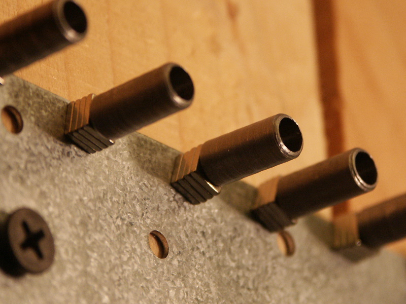
In the resting position (no current), the steel slug and magnets sit on the top of the solenoid, because the steel slug fits inside the solenoid bore but the magnets do not. Also, we've placed another rubber washer here (not shown in this photo, but in many others on this page). This rubber washer sits on top of the plastic solenoid form, and it reduces the unwanted noise made when the magnets fall back down and collide with the plastic solenoid.
Shift Registers and the SPI Bus
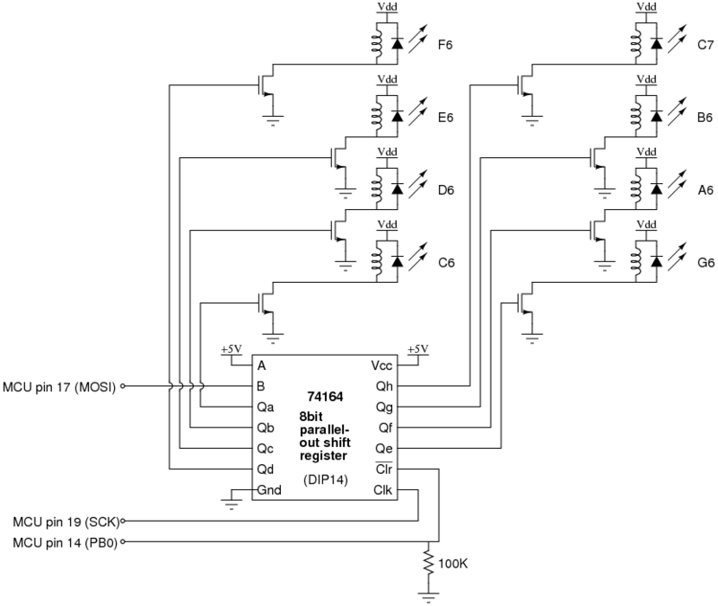
As we explained in the video for this project, we are using a single 8-bit shift register (the Texas Instruments SN74HC164N, or more cordially the '164 chip in the 7400 logic family) to drive our coils instead of driving them directly from our MCU. Given our configuration with only 8 coils, this was not strictly necessary since we had plenty of pins, however a shift register is a very useful tool to have when you need to use more digital output pins than you have on the microcontroller.
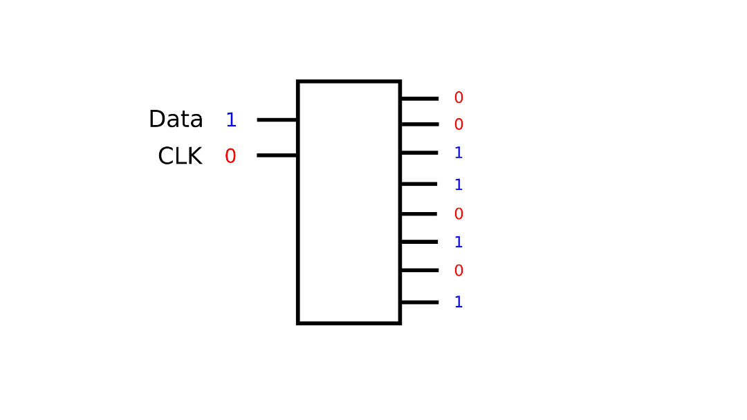
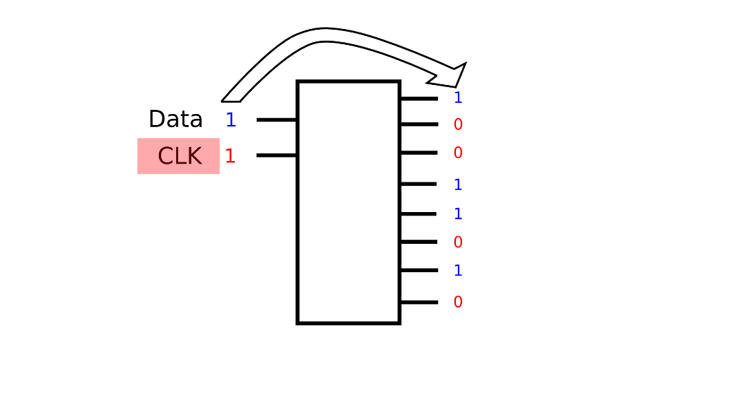
With a shift register, basically bits are shifted into the register one a time, and the shift register shifts its output pins to manifest the series of bits you shifted in. Shift registers give us a way to turn a serial input into a parallel output. The neat thing about this idea is that you need only 2 pins to drive the 8 pins of the shift register. Even more interesting is that you can chain more than one 8-bit shift register together and then be able to shift out 16 bits (or 24, 32...) with the same 2 pins.
One thing to note that we did not have time to talk about in the video is the fact that as the SPI bus shifts out the bits to the shift register, any note we want on will cause a bit to shift across all the earlier coils. This means that as an "on" bit shifts across the previous coil on its way to play a note, it will momentarily turn those coils on for a very very small amount of time (less than a microsecond, compared to the many milliseconds that a firing coil will be allowed to stay on). This is not long enough for the slug to begin moving, but it is worth mentioning here in case you choose to use a shift register in your own application. This is not always the case with all shift registers. Some shift registers do not present the bits on the output until you pulse a certain input to "latch" the bits you have shifted. In that case, the bits would not be presented on the output of the shift register until you pulse this latch line. In our application, the momentary blit of the bit across does not really make a difference.
There is one more input to the shift register that we did not talk about: the output enable input. This pin can be toggled to enable the outputs of the shift register. If this input is held low, the shift register will drive all its output pins low, no matter what bits are being shifted in. You could have MCU drive this pin as a way to quickly clear your shift register, however we have a slightly different use for it in our circuit. We have taken this line and connected it to the programming switch on the circuit of our MCU. Since in the NerdKits setup we use a physical switch to enter the programming mode of the microcontroller, it makes sense for this same switch to also cause the shift register to become not-enabled. This way, when the switch gets flipped to programming mode, the coils all disenage and we don't accidentally keep running current through them (which might cause the coil or MOSFET to overheat) while we are reprogramming our chip.
Full Circuit
As discussed in the video, we used MOSFETs as switches for each solenoid coil, driven by a shift register. The schematics below show how the shift register and MOSFETs together let us control 8 coils from just two digital outputs. For more information about driving inductive loads, check out our Motors and Microcontrollers 101 video.
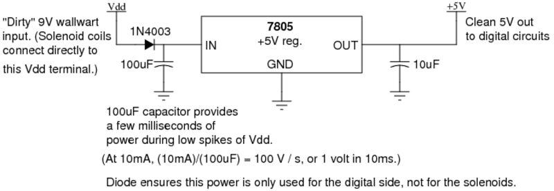
Another issue was power regulation. We powered our xylophone from a 9V DC wall adapter (which we include in our LED Array Kit), but the sudden demand of current when any solenoid is turned on causes the wall adapter's output voltage to dip. This can affect our digital circuits, potentially stopping the microcontroller or causing memory corruption. In order to decouple the noisy power handling from our low-current digital ciruits, we used a diode and a large electrolytic capacitor at the input of the 7805 linear voltage regulator. With the digital circuit requiring very roughly 10mA of current, a 100uF capacitor will discharge at 100 V/s, or 1 Volt in 10ms. If the capacitor is normally charged to 9V and the 7805 will keep running down until its input reaches 7.5 volts, we have 1.5 volts allowable drop, or about 15ms. This cushion lets us ensure our digital circuits get smooth power and continue operating properly.
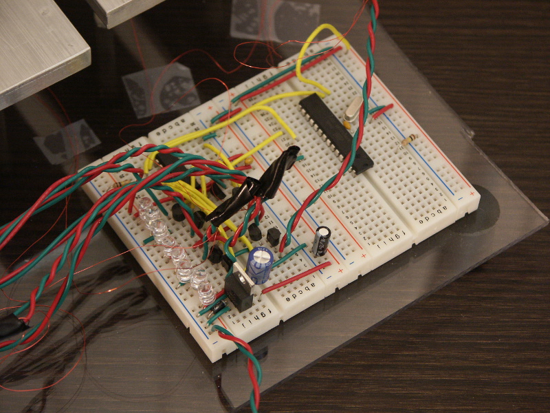
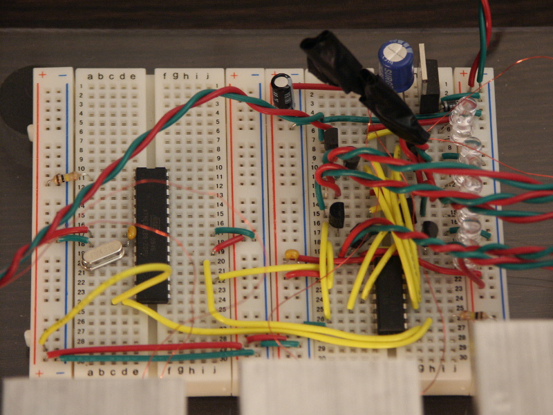
We constructed the circuit on two small breadboards: one for our USB NerdKit-based microcontroller circuit, and the other for our shift register, MOSFETs, flyback LEDs, and power regulation.
Source Code
If you you want to attempt this project it might help you to browse the source code.
More Videos and Projects!
Take a look at more videos and microcontroller projects!
Comments
|
Did you know that you can impress a loved one with a digitally-controlled Valentine's Day Card with randomly twinkling LEDs? Learn more...
|


Copyright © 2013 by NerdKits, L.L.C.