Capacitive Touch Sensor: Learn Electronics with a Spooky Halloween Project

Halloween is a great time to put your engineering prowess to work on a fun project. For this special Halloween project we built a spooky candy bowl that lights up when an unsuspecting trick-or-treater reaches in. While devices like these do exist, many of them use complicated proximity sensors to spring their trap. Here at NerdKits we enjoy doing things a bit differently, and making it easy for you to undertake it as a DIY project. Our proximity sensor is made using nothing but a NerdKit, two pieces of aluminum foil, and some paper clips!
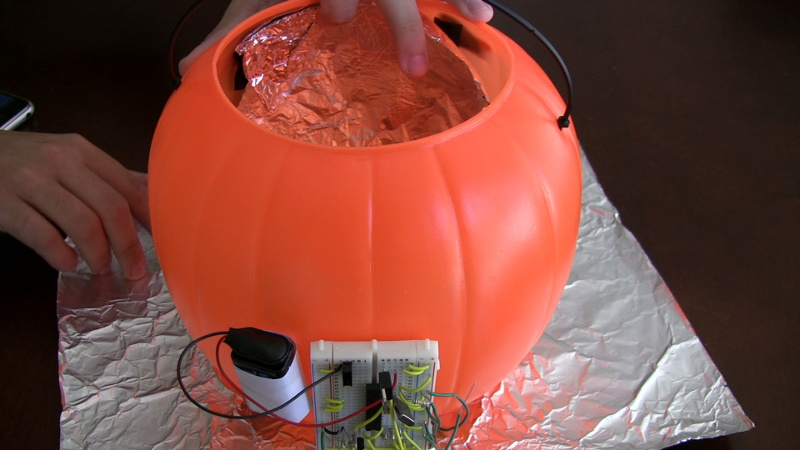
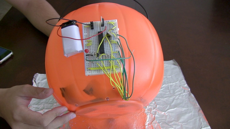
Here are some photos of the capacitive touch sensor project: (click photos to enlarge)
The Capacitive Touch Sensor
The actual sensor used to detect the presence of a hand in explained in detail in the video, but here is an overview. Our sensor operates on the same principle that a capacitive touch sensor works on your laptop touchpad. These capacitive touch sensors work on the premise that humans are mostly water. When you get near an electric field you alter the capacitance enough to be noticed by the sensor.
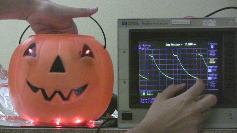
In our system we set up an RC circuit with a capacitor and a resistor in parallel. We use the MCU to charge capacitor up to 5V (a digital high voltage). Then we turn the pin into an input pin, which essentially disconnects that node. This allows the capacitor to discharge through the resistor. The amount of time it takes the capacitor to discharge will be related to the resistor value times the capacitance. We pick a resistor value large enough that the RC time constant is long enough for us to measure with the MCU. In this case 100K ohms worked great. The sensor in this case is two sheets of aluminum foil, one connected to the MCU pin, and one connected to GND. These two sheets create a capacitor that our MCU is charging and discharging. When your hands move between the two sheets, it alters the electric field, and therefore the capacitance of our tin foil contraption. The capacitor therefore takes longer to discharge, and that is detected by the code on our microcontroller!
It might be possible to implement this with a pin change interrupt, and timing how long it takes for the pin to turn into a logic low level; that is, until the voltage drops low enough to be considered a 0 on the pin. However, we chose a slightly more elegant approach. We use the Analog Comparator on the chip. The analog comparator does exactly what its name promises: it compares two analog voltages and outputs a 0 or a 1 depending on which one is higher. The Analog Comparator also allows you to designate a reference voltage to compare against. This voltage happens to be the bandgap voltage which is about 1.2V. This 1.2V is low enough that it gives the pin plenty of room to discharge from 5V before it changes the output of the comparison. You can do anything you want with the output of the comparison, but the Analog Comparator allows you to set up an interrupt to fire when the output of the comparison switches from low to high (in our case this when the voltage on our capacitor drops below 1.2V). With that we are able to time how long it takes for the voltage to drop, using a simple timer in the interrupt handler.
This is once again a great example of multiple concepts, along with multiple parts of the MCU working together to produce a very nifty result. Something as simple as a slight change in the capacitance can be measured by turning your MCU into an oscillator, and timing how long it takes to discharge.
Capacitance and Electric Fields
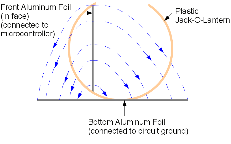
Capacitive proximity sensors work because people are mostly water, and water is a very polar molecule, and is easily turned to align with any applied electric field. In fact, water has a "permittivity" (dielectric constant) that is about 80 times better than air! When a given voltage is applied between the two plates of any capacitor, an electric field is created between the plates. In the region where there's a dielectric, the electric field is actually smaller than it is in air (for water, just 1/80th of the field strength), so your first instinct might be to think that the capacitance decreases as well. However, because the applied voltage must manifest as a product of electric field and distance, the electric field strength in the non-dielectric regions actually goes up substantially. Overall, the energy stored in the electric field per unit volume of space has to do with the square of electric field strength, so all in all, the stored energy and capacitance both increase when a dielectric is inserted. Here are some sketches that might help: (click to enlarge)
Additionally, you should know that grounding this circuit to a wall ground or water pipe, etc., is not at all required for its proper operation. It works fine running isolated on a battery. That's because it's designed with both sides of the capacitor in mind and is a self-contained system. (Some other designs require their sensor system to be electrically grounded to the earth ground, but that's because their designs rely on that as being one plate of the capacitor.)
The Spooky Jack-O-Lantern
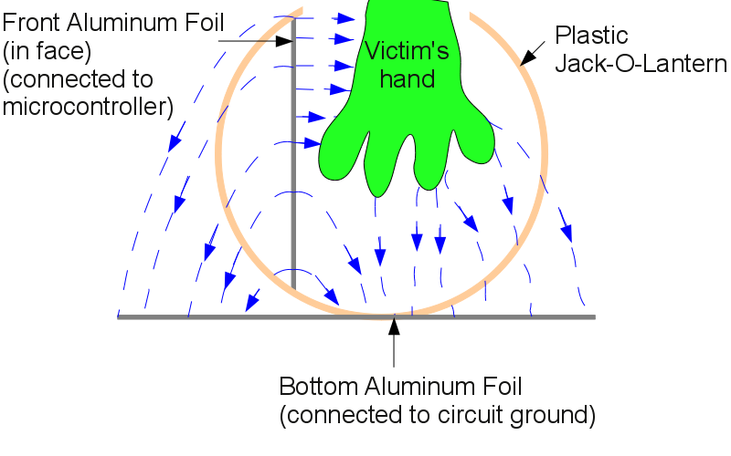
We applied this sensor to create a spooky Halloween Jack-O-Lantern whose eyes glow when you reach inside. One sheet of aluminum foil is taped inside the front face of our Jack-O-Lantern, and connected with a paper clip and a wire to the MCU pin. Another sheet is placed below the jack-o-lantern and connected to the circuit's ground. These two sheets make up the capacitor, and a hand between them will be detected by our capacitive proximity sensor. There is also a 100K ohm resistor between the MCU pin and GND to complete the RC circuit.
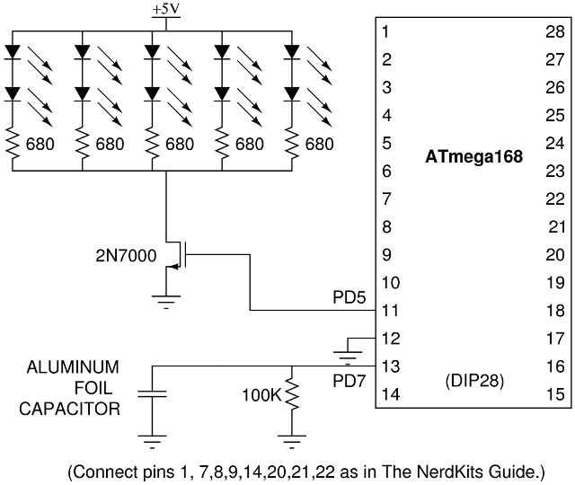
We also use the MCU to turn on LEDs that we have mounted on our Jack-O-Lantern (Coincidentally, this is what is amazing about microcontrollers, you can read sensors and react by doing something cool!). We use a PWM output of the pin to output a PWM signal whose duty cycle is controlled with how deep in the bowl your hand is. Notice that in this case we are driving all the LEDs with a single output. The MCU can't source that much current without inducing noise in our analog measurement, so instead we use a 2N7000 transistor to control when the LEDs are on and off. The output of the PWM pin is connected to the gate, and the LEDs are connected with a current limiting resistor to the transistor.
The schematic of this project is shown below.
The Code and the Analog Comparator
In this project we once again are using mostly components and concepts we have used before. We are just piecing them together in a new way to do something interesting. We set up to different timers, one to run the PWM output, and one is used to time the number of clock cycles it takes the capacitor to discharge. For more complete explanation of the PWM pins and how they work take a look at our Servo Squirter tutorial.
The code also uses the Analog Comparator to compare the voltage across our capacitor to a reference voltage. When the voltage becomes lower than the reference voltage we set it up to fire an interrupt. The functionality and configuration of the Analog Comparator is explained in detail on the ATMega168 Datasheet starting on p243. Take a look at that the datasheet and compare it against what we do in the init_analog_comparator() function to see how we set up our analog comparator to fire an interrupt at the right time.
The interrupt handler itself is not very complicated. It merely changes the pin on the capacitor to an output pin so it can charge it up to 5V. Then it records the time, and sets the pin back to an input pin so it can start letting the voltage drop. When the voltage drops low enough, the interrupt will fire again. We use the interrupt to calculate an average of its readings over time, and only give the main loop an average reading over many samples. Take a look at our Interrupts: Interfacing with a PS/2 Keyboard video for more about interrupts and things you should be aware of when using them.
The main loop is only concerned with setting the value of OCR0B correctly to control the PWM duty cycle of the LEDs. This actually turns out to be a more complicated thing than you would expect. You could cut out most of it out and still have a working system, but we use a little bit of software to make the system more robust. The main loop continuously adjusts the "baseline" level that it expects to see on the timer of the voltage drop. This is done to account for variations in the capacitance of the foil over time. To accomplish that we use a simple low pass filter that weighs the old value much more heavily than the new value it just saw.
baseline = avg_timer*.003 + baseline*.997;
Notice how we come up with a new baseline value, by using a tiny fraction of the current value plus a large fraction of the old value. That scheme works great, except that it means the system would adjust the baseline when a hand lingers in the bowl for too long. To counteract that effect we keep track of large sudden spikes in the capacitance reading (indicating a human hand), and simply don't adjust the baseline for a while after that. This allows the baseline to not change for hands coming in and out, but it will adjust eventually to permanant changes (like crumpling aluminum foil, or changing candy levels).
The last thing we need to do is use a little bit of algebra to convert the time values from the interrupt handler to a number between 0 and 255 to set the PWM output. By observation of the early prototype we noticed that there was about 5% variation in the reported values between the baseline and when a hand was in the bowl. We use a little bit of math to convert values between the baseline and baseline+5% into values from 0-255. Line 182 in our code takes care of this conversion.
Parts List
Beyond our USB NerdKit, you will need:
Source Code
You can download the source code here.
Other Resources
An Application Note from Microchip, "Capacitive Sensing with PIC10F" may be of interest to readers.
More Videos and Projects!
Take a look at more videos and microcontroller projects!
Comments
|
Did you know that NerdKits also has extra parts available for its customers? Learn more...
|


Copyright © 2013 by NerdKits, L.L.C.